Multi-domain Assessment of a Kinetic Facade
Determining the Control Strategy of a Kinetic Facade using BIM Based on Energy Performance, Daylighting, and Occupants’ Preferences
Sign in and Register
Create an Account
Overview
Abstract
An assessment workflow was created to simulate and evaluate the performance of a kinetic facade in an interior space. It includes parameters of energy performance, specifically, solar heat gain through the window, daylighting, and the occupants’ behavior. The solar heat gain was calculated based on the detailed calculation method in the ASHRAE handbook. The daylighting metric used was illuminance value and was based on the algorithm of DOE-2 daylighting. Custom nodes in Dynamo were created in Python to calculate relevant parameters. The control strategy of the kinetic facade was determined through the combined use of Dynamo and Microsoft Excel by balancing solar heat gain and illuminance value on the work plane. The criterion for determining the control strategy was to avoid the direct glare, maintain illuminance value between 500 lux to 1500 lux, and meanwhile regulate the solar heat gain based on real-time weather. Occupants can overrule the facade control based on their preferences. The program showed the tradeoff by comparing solar heat gain between the user’s choice and the theoretical optimum value and the change of lux level on the work plane in order to realize real-time control. A dashboard was created as the visualization interface for the occupants.
Authors

Kunyo Luo
Master of Building Science
University of Southern California

Karen Kensek, LEED AP BD+C, DPACSA
Professor of Practice
USC School of Architecture
kensek@usc.edu

Marc Schiler, FASES
Professor
USC School of Architecture
marcs@usc.edu
Keywords
1. Introduction
Kinetic façades can play a significant role in modern architecture as they can serve as sun protection devices to prevent excessive solar radiation entering indoor spaces reduce heat gain during the summer and eliminate direct glare. The control strategy of many kinetic façades is based on a single factor, either climate boundary conditions such as solar radiation, temperature, wind speed, etc., or room/material states such as operative temperature and daylight illuminance, or controlled by the occupants directly (Loonen, 2017). Kinetic façades can play a more important role in terms of their energy performance and potential to control the daylight architecture especially if one could create a simpler method to analyze their performance during the early design stage and take occupants’ behavior into account.
Building information modeling (BIM) software (e.g. Autodesk Revit) contains and stores not only the geometry, of a building but also data. Using Dynamo, a visual programming platform embedded in Revit, the user can create customized tools for either simplifying existing functions or realizing new functions, in this case, a tool for studying the trade-offs of heat gain, daylighting, and occupant preference.
1.1. Kinetic Façade
In the past few decades, kinetic façades have played a more important role as alternatives to static building envelopes as they are designed for meeting the diverse and complex demands in terms of occupant comfort, energy efficiency, and cost efficiency (Sharaidin, 2014). While the energy performance of the building in real life remains to be evaluated, kinetic facades represent a new wave of architecture components that put less pressure on active HVAC and lighting systems and more on the manipulation of passive effects (Risen, 2017). That concept has been described in a number of ways, ranging from the usage of innovative components to highly complex designs and advanced technological application (Sharaidin, 2014).
It is difficult to model a kinetic façade accurately in most energy software programs. The form of kinetic façade elements can vary from project to project, from a simple folded plate like the MegaFaces in Sochi, Russia, designed by Asif Kahn (Grozdanic, 2016), to complex geometry such as the Al Bahr Towers in Abu Dhabi, designed by Aedas UK (CTBUH, 2013). Many energy simulation programs cannot recognize a complex panel as a shading device and creating complex geometry in them can be difficult. For example, only horizontal overhang and vertical fin are available shading devices to choose in eQuest. If users want to simulate a more complex shading element, the complex panel geometry has to be simplified, maintaining the same opening ratio (Kim et al., 2015). Importing from Autodesk Revit is an available way to create an energy model in IES-VE and DesignBuilder, but when the geometry is too complex, the quality of the imported model cannot be guaranteed (Sharaidin, 2014).
1.2. Solar Heat Gain
When solar radiation hits the glass of a window, the ability of the material to transmit or resist the solar heat gain is referred to as Solar Heat Gain Coefficient, SHGC (Lee, et.al, 2014). It is a dimensionless number that varies from 0 to 1. Solar radiation incident on the glass always consist of two components: direct solar radiation and diffuse solar radiation. SHGC is divided into two types based on the type of solar radiation. The SHGC for direct solar radiation is expressed as SHGC(θ), and SHGC for diffuse solar radiation as [SHGC]D (Lee, et.al, 2014).
Solar heat gain through the window is an important component of cooling load of the building, especially for those high-rise buildings where curtain wall systems are applied and therefore have large glass area on the façade. Excessive solar heat gain through the transparent (or translucent) part of the façade during the summer seasons can lead to overheating and will degrade thermal comfort of interior space. Although the direct relationship between solar heat gain and thermal comfort is undefined currently and there are also no prescriptive requirements for solar heat gain in main energy codes and standards (e.g. LEED, ASHRAE, and Title 24), it can be assumed that reduction of solar heat gain in summer will have a significant contribution to reducing the cooling load and therefore energy consumption by AC and indoor thermal comfort. Based on the assumption, solar heat gain through the window can be an indicative factor to assess the energy performance of kinetic façades.
The calculation method of solar heat gain is defined in the ASHRAE handbook (ASHRAE, 2013). In the calculation, the solar heat gain through fenestration is divided into two parts: direct solar heat gain and diffuse solar heat gain. Relevant parameters include window area, sun position, solar radiation level on exterior horizontal plane, solar heat gain coefficient (SHGC) for both direct sunlight and diffuse sunlight, and several introduced factors that consider the effect of shading devices. Solar heat gain was used in this project instead of more detailed energy calculations. Early design decision making may not require a detailed energy simulation in terms of dealing with massing, form-finding, or other early design problems (Crawley et al., 2008).
1.3. Daylighting Metrics and Calculation
Although the visual quality of interior space cannot be described by horizontal illuminance completely, one of the common daylight metrics to evaluate the adequacy of illumination of indoor space is illuminance on the horizontal plane (Mardaljevic, 2009). It typically indicates the lighting level that is required for visual tasks. For office or clerical work, a value of 300-500 lux is recommended, and most artificial lighting systems are designed based on this criterion to reach the required level of illumination (Rea, 2000). The way to simulate and evaluate the horizontal illuminance is usually specifying a grid of points on the horizontal plane, either on the ground level or desk height level, etc. and the defined horizontal plane could either be certain points, specific areas or zones, or a continuous grid (Mardaljevic, 2009).
The daylighting calculation method used in this research is based on the DOE-2 Daylighting Calculation (Winkelmann, 1985). According to the algorithm, the total illuminance on a reference point consists of two components: direct component which is basically from the sun or sky directly, and internal reflected component which mainly from the reflectance of the light from interior surfaces (walls, ceiling, and floor). The direct component of indoor illuminance is the function of three parameters: luminance of window element, solid angle subtended by window element with respect to reference point, and the angle between vertical and ray from reference point to the center of window element.
Among those three parameters, luminance of window could be calculated based on sun position and sky condition, and the solid angle requires geometric analytics because it contains large amount of repetitive calculation including the angle, distance between reference point and each of window element. Therefore, to calculate solid angle, the window surface is divided into a x-y grid of elements, and the illuminance value on the reference point depends on the summation of the solid angle subtended by each window element, including those elements shaded by either the façade component or surrounding obstruction buildings, and also those elements exposed to the sun or sky directly. The difference of the background luminance of the shaded elements (use luminance value of shading device in calculation) and unshaded elements (use luminance value of sun or sky in calculation) leads to the different result of illuminance value on the reference point. Therefore, it is necessary to separate them into two groups based on the position of the kinetic façade component and the exterior obstruction building and then calculate the total solid angle value for the two groups of window element separately.
1.4. Impact of Occupant Behavior
In contrast to conventional, static facades, kinetic facade systems can have an interdependent relationship with building occupants (Loonen et al., 2017). In some applications, the simulation model needs to be able to evaluate not only how the kinetic façade component affects indoor environment (e.g. solar heat gain and daylighting), but also how individual occupants may want to control a specific adaptive building envelope technology (Haldi and Robinson 2010).
Due to the nature of occupants’ behavior, which is hard to predict and seems relatively random, and the existence of other uncertainty factors (e.g. site weather conditions, equipment, and internal heat gain, etc.), large discrepancies exist between predicted and actual energy performance (Sun, 2015). From an occupant behavior’s point of view, apart from the occupant schedule, occupants’ actions on façade control are also a significant factor. Sometimes even though the occupant schedule remains the same, the different actions that an occupant can take during specific time periods could make a difference. For example, the occupants might want to overrule the existing control program because of the view out the window. A possible situation is that occupants open the kinetic façade component completely at certain times because they want to have a better view out, even though it will compromise energy performance or daylight quality. Therefore, a program should be able to inform the user and let them understand how their behavior will impact the façade performance.
1.5. Building Information Modeling (BIM), Visual Programming, and Python
“Building Information Modeling (BIM) is an intelligent 3D model-based process that gives architecture, engineering, and construction (AEC) professionals the insight and tools to more efficiently plan, design, construct, and manage buildings and infrastructure” ("What is BIM", 2017). BIM provides users a modeling platform that contains all of the building components with specific data and information like geometric parameters and material properties, which enables the efficient generation, documentation, and management of building information (Kim, 2015). In addition, the application programming interface (API) gives BIM the ability to be integrated with other simulation and analysis such as daylighting, solar radiation, and energy consumption (Kim, 2015).
One commonly used BIM software program in the building industry is Autodesk Revit. It has been already widely used for many different domains, including architecture, structure, mechanical system, construction, etc. (Rahmani Asl, 2015). In Revit, the structure of its component library is constructed based on the order of category, family, type, and instance, and specific information that related to the objects (Kensek, 2014). Parametric modeling and analysis is possible in Revit by manipulating the object directly or changing the related parameters.
Computer programming is a powerful and useful tool for designers to deal with complicated and sophisticated design problems in a relatively easier way (e.g. using for-loop and conditional statements to solve repetitive or large numbers of calculations) especially in parametric design process (Boeykens and Neuckermans, 2009). For those designers who don’t have strong programming skills or without computer science background, visual programming interfaces could be an alternative of traditional text coding with a visual metaphor of connecting small blocks of independent functionalities into the entire system (Boeykens and Neuckermans, 2009). In visual programming interface, users are able to write the script on their own by manipulating function nodes graphically rather than typing code textually (Rahmani Asl etal., 2010). Dynamo is the visual programming tool for Autodesk Revit.
Python is a widely used programming language of general-purpose programming. Python is an object-oriented language that emphasizes the code readability and syntax simplicity ("Python (programming language)", 2017). Users are able to write their own package or module to realize certain customized functions, and those published packages and modules can also be used by other users and embedded into other applications. Python can be using inside of Dynamo.
2. Methodology
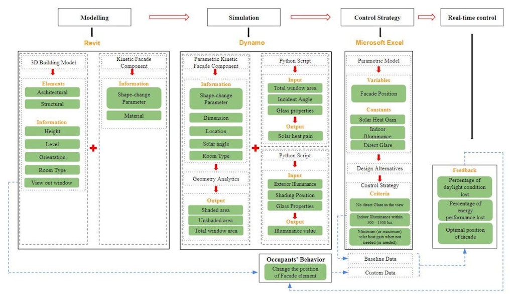
Software programs that were used in the workflow include Autodesk Revit, Dynamo, and Microsoft Excel. Basically, there are four main steps involved in this workflow: 1) prepare the building geometry prepared and make the kinetic façade element in Revit; 2) load them into Dynamo and make them parametric, calculate the hourly value of solar heat gain and indoor illuminance; 3) collect hourly data in the Excel for further processing and analysis in order to find the optimum façade position for each hour, and 4) introduce occupants into the workflow for real-time control (Fig. 1).
2.1. Workflow Overview
The energy performance of the kinetic façade is done at a façade-component scale, because many necessary factors and parameters for calculating energy consumption of the entire building remain unknown, especially during the early design stage, such as detailed information and schedule of the mechanical system. In addition, in terms of the façade-component scale simulation, instead of calculating how much solar radiation hit on the façade like most of the projects and research did, to be more descriptive and indicative, solar heat gain through the window with kinetic façade is calculated based on the calculation method provided by ASHRAE handbook (ASHRAE, 2013).
Another important aspect to evaluate about the kinetic façade is the daylight condition. For more accuracy and reliability, hourly indoor illuminance is calculated based on the algorithm used in DOE-2. A Python script was developed to deal with a large amount of repetitive calculation. Due to the versatility of the DOE daylighting algorithm, which can also calculate the glare index and hourly lighting energy use, it is possible and maintain the potential to extend the Python script for further analysis apart from indoor illuminance.
The hourly data of solar heat gain and indoor illuminance is integrated for further analysis in terms of finding control strategy. The criterion of operation scenario of a kinetic façade includes indoor illuminance value reaching the target lux value with a certain level of precision (e.g. 500 lux for office) and solar heat gain staying as low as possible during the summer seasons.
In terms of the occupants’ preference on view out of the window (or just to let more light in or keep more daylight out), a custom perspective view from indoor space can be set through Dynamo. If the occupants would like to overrule the current position of the kinetic façade component, the value of solar heat gain and daylighting illuminance are recalculated under the new condition. The result is compared with the optimal one that derived from previous calculation. Then, feedback is presented to occupants informing them the discrepancies in energy performance and daylight quality (or even energy cost based on artificial lighting use and cooling and heating load) between their personal choice and the theoretical optimal command.
Compared with the commonly-used Rhino and Grasshopper-based research methodology, manipulating with Revit directly can let the designers access to not only 3D geometry at the very beginning of the design process, but also information of the building elements such as material properties, giving them insight that how varied materials can make a difference in design. And after the design, documentation and information management can be more straightforward and efficient by working in Revit and Dynamo directly.
2.2. Workflow Details
2.2.1. Modeling in Revit
The building geometry and kinetic façade geometry is created in Revit with specific parameters set, and prepared for simulation and analysis later. The building model in Revit should contain the geometry of the wall, the roof, the window, and the floor. Furthermore, the data of the dimension of primary building components, building orientation, position, dimension, type of the window, primary nearby building obstruction (if applicable), and the use of interior space, etc. should be specified.
The kinetic façade geometry is created in Revit first and then is loaded into Dynamo for further simulation and analysis. Considering the variety of types of geometry in Revit, such as common building components (wall, roof, etc.), in-place components, adaptive family components, and masses (conceptual mass or in-place mass) geometry, etc., the new workflow is able to incorporate different types of Revit geometry as much as possible. The façade component can be created from the generic adaptive family, conceptual mass, and in-place model, or other adaptive families that could be used to create façade component (e.g. curtain panel pattern-based family).
2.2.2. Simulation in Dynamo
After the building geometry and façade geometry is prepared, all simulation including solar heat gain and indoor illuminance calculation is conducted in Dynamo. Most simulations in Dynamo are done through a series of Python nodes. In order to simulate and evaluate the performance of the kinetic façade system, eight custom nodes were created in Dynamo through Python scripting. The primary and key custom nodes include 1) solar heat gain calculation, which is for calculating the value of solar heat gain based on ASHRAE standards; 2) indoor illuminance calculation, which is for calculating the value of illuminance of one or more specific point inside based on the algorithm of DOE-2 Daylighting calculation; 3) geometric analysis, which is for finding the shadow pattern of the façade element on the window and calculating relevant parameters.
2.2.3. Solar Heat Gain Calculation
For a detailed solar heat gain calculation of the kinetic façade’s shaded area (shadow area) on the glass is accurately determined. Unlike the methods that were proposed by previous studies to find the shadow area, including using the coordinate system and polygon method (Lee, et.al., 2016), this can be done in Dynamo in a faster and parametric way. In order to avoid having a crowded and complex script in Dynamo and to be friendly to the users, a custom node was created by programming in Python. For this custom node, the input parameters include the outline of the exterior shading device or façade component (perimeter curves), the glass surface (the input surface could be either one single surface or a list of surfaces), a vector that indicates the true north, sun altitude, sun azimuth, and a Boolean to decide whether to display short lines that point to the sun direction. The output of this node includes a poly surface that represents the shadow on the glass, unshaded fraction value, and exposure coefficient value, which allows users to visualize the effect of a shading device both graphically and textually. These two output numbers were stored for the later solar heat gain calculation.
The calculation process of solar heat gain takes into account factors such as glass area, position of the kinetic façade (or shading), exterior solar radiation level (both direct and diffuse radiation), incidence angle of sunlight, thermal and optical properties of glass material and shading material (Fig. 2).
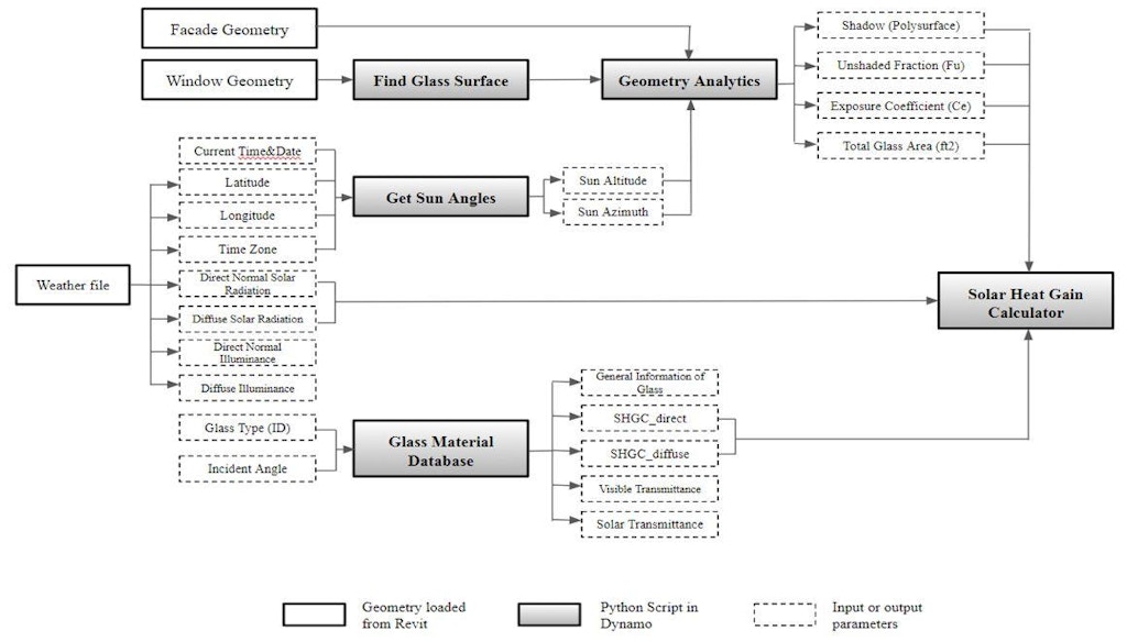
The node “Get Sun Angles” is used to calculate sun azimuth and sun altitude for specific time at a specific location. The input parameters of this node include latitude, longitude, time zone, and current time in hour. The first three parameters are derived from EPW weather file directly. The output sun azimuth and altitude become input parameters for solar heat gain calculation node.
The node “Glass Database” is created to store a large amount of data of glass materials, including glass type, thickness, visible transmittance, solar heat gain coefficient (SHGC) for direct light under different incidence angle and diffuse light, and also solar transmittance under different incidence angle. The original data of glass is from the ASHRAE handbook (ASHRAE, 2013), chapter 15, which provides the value of SHGC, solar transmittance, hemisphere directive reflectance under incidence angle of 0°, 40°, 50°, 60°, 70°, and 80°. Considering the limited number of incidence angle, which is not continuous and therefore hard to get the SHGC value, and that looking for a specific data from a large table is relatively time-consuming and unrealistic during the design process, this custom node for data storage was created. This node not only stores the existing data, but also applies the algorithm to interpolate the SHGC value under any given incidence angle (assume linear relationship between every two adjacent integer angles), which is able to give SHGC value for any input incidence angle specifically. Designers only need to input glass ID and the incidence angle to get all needed parameters mentioned above. The database could be extended and adjusted based on the available glass products or if some specific data are provided by the manufacturer.
The node “Solar Heat Gain Calculator” is created to calculate solar heat gain for either a single hour or some other period of time. The calculation is conducted based on user-specified parameters and those parameters provided by previous custom nodes (“Get Sun Angles” and “Glass Database”). The input parameters of this node include hourly exterior direct and diffuse solar radiation, glass area, unshaded fraction (Fu), exposure coefficient (Ce), exterior attenuation coefficient (EAC), and SHGC for direct and diffuse light. It outputs the hourly solar heat gain data with the default unit of Btu. Data visualization is also available for this node, by generating 3D bar chart representing the hourly data, which was colored according to the corresponding value. Four Booleans are set to control and modify the output parameters. The units of the output solar heat gain could switch from Btu to Watt by assigning “True” to the first Boolean variable. The output solar heat gain value could be represented in summation format instead of hourly data by assigning “True” to the second Boolean variable. Users could choose to not display the 3D bar chart for visualization by assigning “True” to the third Boolean variable. Users could also choose to not display the trendline that indicates the tendency of hourly solar heat gain data by assigning “True” to the fourth Boolean variable.
2.2.4. Daylighting Calculation
Although many sophisticated computer programs for daylighting simulation (e.g. Radiance) are available, it is sometimes unrealistic for the architects or designers to conduct a sophisticated daylighting simulation in those programs, especially when hourly data is possibly needed to determine the control strategy of the kinetic façade system. Therefore, to make the workflow easier as well as consistent and let designers be able to simulate and evaluate the daylight condition of interior space under the effect of the kinetic façade during their design phase, a custom node in Dynamo was created by programming in Python. This custom node gives the illuminance value at the reference points (user-specified) in the interior space and provides a general idea to designers that how to design the façade system to balance energy performance and daylighting (Fig. 3).
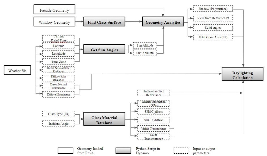
As mentioned previously, the algorithm for the daylighting calculation is based on DOE-2 Daylighting Calculation method, which was developed by Lawrence National Laboratory, UC Berkeley. Basically, the DOE-2 daylighting calculation algorithm has three main stages. In the first stage, a preprocessor calculates the daylighting factor for later use in the hourly energy calculation. The factors that are taken into account include the distribution of sky luminance, window size and orientation, glass transmittance, inside surface reflectance, exterior shading devices, and obstruction, etc. In stage two, hourly daylighting calculations are conducted for daylight hours. Then, the indoor illuminance value from each window is found by interpolating the stored daylighting factors using the current sun position and cloud cover and multiplying the current-hour exterior horizontal illuminance value. Glare can also be analyzed by calculating the analogous glare index and then comparing with pre-defined comfort level. In stage three, the lighting control is simulated to determine the electrical lighting energy needed to make up the difference between the target lux value and daylighting level. In this case, the third stage will not to be performed. In this custom node, only the steps that calculate hourly indoor illuminance and glare index are conducted. Glare index is not calculated in this custom node, and glare is determined simply by whether the sun is visible through the window from the occupant’s view.
This illuminance calculation has been previously validated by comparing the DOE-2 calculation results with scale-model measurements made in the Lawrence National Laboratory, and with SUPERLITE, a quite detailed and sophisticated illuminance computer program (Winkelmann, 1985).
2.2.5. Determining the Control Strategy
The control strategy was determined for balancing the direct glare, the solar heat gain through the window, and the indoor daylight illuminance. The basic criterion is to obtain the minimum amount of solar heat gain when it is not needed and maximum of solar heat gain when it is needed and maintain the indoor illuminance value within 500 lux to 1500 lux simultaneously.
The sequence of daylight quality (indoor illuminance) and energy performance (solar heat gain) can switch with each other, which means either illuminance or solar heat gain can be the parameter to be considered after glare. In general, the criterion for the indoor illuminance is to maintain it between 500 lux and 1500 lux, and the criterion for solar heat gain is to minimize its negative impact when it is not needed (during the daytime of the summer seasons) and maximize its benefit when it is needed (during the early morning of the winter seasons). Whether the solar heat gain is needed is determined through comparing the hourly outside ambient temperature with the thermal comfort range that recommended by the ASHRAE standard. The simple thumb of rule for solar heat gain is that when the outside ambient temperature is higher than the high bound value of the comfort range, solar heat gain might cause overheat of indoor space, therefore it is not needed. When the outside ambient temperature is lower than the low bound value of the comfort range, solar heat gain can help heat up the indoor space, therefore basically it is needed.
In summary, the control strategy of the kinetic façade was decided through the combined use of BIM (Revit and Dynamo) and Microsoft Excel.
2.2.6. Occupants’ Behavior
As the kinetic façade changes its form responding to outdoor environment condition, the view out through the window will change. The occupants might have their own preference on that. To get the occupants involved and provide real-time control, the occupants are able to overrule the façade control. When the façade position is changed by the occupants, the solar heat gain and indoor illuminance value will be recalculated and then compared with the theoretical optimal data, letting the occupants know that how their behavior can affect the performance of kinetic façade (Fig. 4).
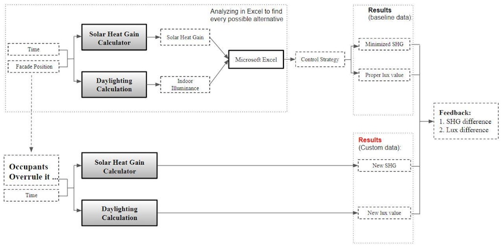
When the occupants overrule the façade controls to get a better view out the window, the difference between the new façade position and the theoretical optimum façade position generates the value of difference in solar heat gain and indoor illuminance, which can inform the occupant that how their behavior will affect the performance of the façade system. The comparison results were presented through a custom dashboard, which allows the occupants to observe the façade position from both exterior and interior view, as well as to visualize the façade performance (solar heat gain and indoor illuminance) through the colored columns and text.
2.2.7. Python Script
In all, Eight custom nodes in Dynamo were created in order to accomplish the workflow: Get Sun Angles, Glass Database, Solar Heat Gain Calculator, Find Shadow on the Window, Luminance Distribution Calculator, Solid Angle Calculator, Internal Reflect Component Calculator, and Solid2PerimeterCurve. The method for determining the operation scenario of the kinetic façade was to combine Dynamo and Microsoft Excel. Geometry-relevant parameters such as unshaded fraction (Fu) and exposed coefficient (Ce) can be obtained from Dynamo dynamically, and then the solar heat gain and indoor illuminance can be calculated. The data was exported to Excel and for analysis and comparison to find the optimum position of the façade.
The occupants are allowed to overrule the façade control based on their preference on the view out the window. The discrepancy of façade performance due to the occupants’ behavior was displayed and visualized through a dashboard, which contains the information of the façade position, time, the difference of solar heat gain value and the difference of illuminance value between the optimum scenario and occupant-intervened scenario.
2.2.8. Data Processing and Analysis
All of the data is exported automatically to Excel for further processing and analysis. Dynamo provides built-in function “Write to File” to export data list into Excel. For each specific hour, there will be multiple groups of data that represent the different position of the kinetic façade and the corresponding value of solar heat gain and indoor illuminance. The optimum operation scenario will be determined based on the dataset.
3. Case Study
The case study demonstrated that the proposed method is applicable to decide if there is a direct glare problem, to calculate solar heat gain through the window and indoor illuminance on the work plane dynamically, and to evaluate the performance of a kinetic façade. The effect of the occupants’ behavior (occupants overrule the control of kinetic facades based on their preference on the view out the window) can also be visualized.
3.1. Geometry
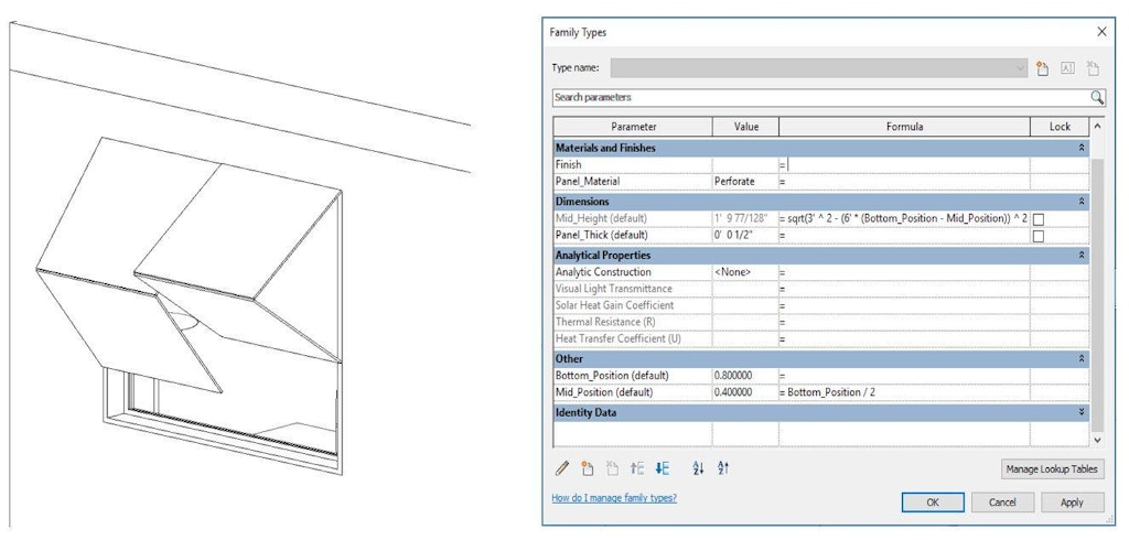
In the case study, a simple house with a south-facing window was used, and the kinetic façade consists of two foldable panels that are controlled and moved together. The parameter in Revit that controls the position of the kinetic façade is “Bottom_Position”, which has 6 values varying from 0 to 1 with the increment of 0.2 (0, 0.2, 0.4, 0.6, 0.8, 1.0) (Fig. 5).
Two dates, August 21st and December 21st, were selected to represent the summer and winter seasons based on the climate analysis for Los Angeles. For each of those days, hourly conditions (from 7 am to 6 pm) of the direct glare, the solar heat gain, and indoor illuminance were conducted, and for each hour, all six possible façade positions were simulated. Based on the results, the most proper façade position for each hour was determined, and then the control strategy of the kinetic façade was determined. The criterion for finding the façade position includes three steps: 1) the kinetic façade should block the direct sunlight in the occupants’ view to avoid direct glare; 2) the indoor illuminance on the work plane should be within 500 lux and 1500 lux; and 3) the position of the shading device should minimize (or maximize) the solar heat gain during the period that the solar heat gain is not needed (or is needed). Occupants can overrule the control of the kinetic façade based on their personal preference, and a dashboard showed the effect of occupants’ behavior by presenting the possible discrepancy of the solar heat gain and indoor illuminance between the theoretical façade position and the overruled façade position.
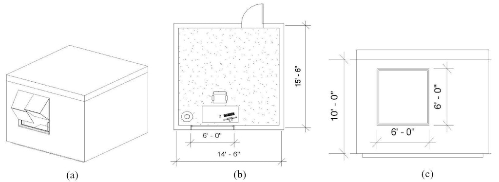
The building model for the case study is a very simple space that only contains one single room for office use, and it was created in Revit (Fig. 6). The building is 14’-6’’ x 15’-6’’ and is 10’ high. The 6’x6’ window in this space is south-facing, and the glass type of the window is uncoated double glazing.
3.2. Analysis
According to the DOE daylighting calculation algorithm, the total illuminance on the reference point consists of two parts: the direct component that is from the sun or sky directly, and the internal reflected component that is mainly from the reflectance of the light from interior surfaces (walls, ceiling, and floor). The direct component of indoor illuminance is the function of three parameters: luminance of window element, solid angle subtended by window element with respect to reference point, and the angle between vertical and ray from reference point to the center of window element. The reference point in this case study is 3’ away from window and 3’ above the floor.
Among those three parameters, the luminance of the window could be calculated based on sun position and sky condition. The solid angle requires geometric analytics because it contains a large amount of repetitive calculation including the angle and the distance between the reference point and each of the window elements. Therefore, to calculate the solid angle, the window surface is divided into a x-y grid of elements, and the illuminance value on the reference point depends on the summation of the solid angle subtended by each window element, including those elements shaded by either the façade component or surrounding obstruction buildings and those elements exposed to the sun or sky directly. The difference of the background luminance of the shaded elements (use luminance value of shading device in calculation) and unshaded elements (use luminance value of sun or sky in calculation) leads to the different result of illuminance value on the reference point. Therefore, it is necessary to separate them into two groups based on the position of the kinetic façade component and the exterior obstruction building and then calculate the total solid angle value for the two groups of window element separately.
3.3. Results of control strategy decision of the case study
The criteria for finding the control strategy of the kinetic facades depends on the climate pattern of different periods in a year as well as the weather conditions within a single day. The primary objective is to reduce the excessive solar radiation coming into the interior space, which will degrade the indoor thermal comfort and therefore lead to the unnecessary operation of the mechanical system in the building, meanwhile to create a visually comfortable environment for the occupants by maintaining the enough indoor illuminance level and avoiding the glare issue caused by direct sunlight in the view sight.
Solar radiation could have either positive or negative effects on indoor thermal environment depending on the season, the real-time outdoor ambient temperature, and indoor set point temperature. Technically, in summer, for a south-oriented building, whether the indoor space needs the solar radiation or not should be determined by the outdoor ambient temperature and the indoor thermal comfort temperature range provided by ASHRAE standard (summer seasons: 75.1 – 80.1 ℉, winter seasons: 68.5 – 75.7 ℉). There could be a few possible situations: 1) during the summer seasons, the outdoor ambient temperature is lower than the low boundary temperature (75.1℉) of the indoor comfort range; 2) during the summer seasons, the ambient temperature is within the recommended comfort or higher than the high boundary temperature (80.1℉) of the comfort range; 3) during the winter seasons, the ambient temperature is higher than the high boundary temperature (75.7℉) of the comfort range; 4) during the winter seasons, the ambient temperature is within the comfort range or lower than the low boundary temperature (68.5℉) of the comfort range. Those four situations should be considered separately to determine if the solar heat gain is needed in specific time.
- In summer, if the outdoor ambient temperature is lower than the low boundary temperature of the comfort range, the interior space needs to be heated up. This could probably happen during the early in the morning or late in the afternoon before sunset (for those cities in the warm or extreme hot climate, this might not happen.), when the occupants inside may feel cold and dissatisfied with the thermal environment. Therefore, getting solar heat gain during those periods is beneficial. Solar heat gain is needed.
- In summer, if the ambient temperature is within the comfort range or even higher than the high boundary temperature of the comfort range, the interior space might be able to maintain the indoor temperature without running air-conditioning or get heat gain from envelope (conduction from walls, windows, etc., and radiation from windows). Generally, this could occur during the most periods of daytime. Therefore, avoiding the excessive solar heat gain during those periods helps to maintain indoor thermal comfort meanwhile reduce the use of air-conditioning. Solar heat gain is not needed.
- In winter, if the ambient temperature is higher than the high boundary of the comfort range, air-conditioning is basically is not needed and sometimes when the internal heat gain is quite large (e.g. office area with lots of electrical equipment and appliance, or shopping mall where has large amount of people.), cooling loads might exist and solar heat gain will make the indoor thermal condition worse. This situation may occur for certain days in winter at noon, but not as frequent as other situations. Therefore, solar heat gain during those periods is not needed.
- In winter, if the ambient temperature is within the comfort range or lower than the low boundary temperature of the comfort range, heating for interior space is needed. Therefore, maximizing the use of solar heat gain can reduce the workload of the heating system and is beneficial for the indoor thermal condition. Solar heat gain is needed.
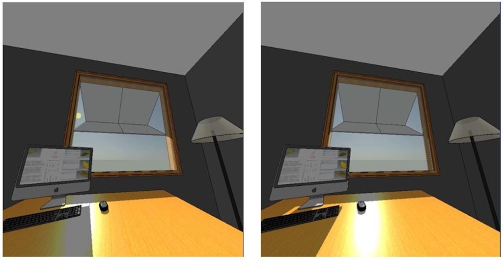
If the sun is visible in the occupants’ view, the occupants will have a glare problem (Fig. 7). Therefore, a simple rule to avoid the glare issue is blocking the direct sunlight, which can be realized by moving the kinetic façade to a proper position. In the case study, the glare issue was considered as the priority or pre-decision, which means even though the illuminance level is acceptable under certain facades’ position, if the sun is visible, the scenario of the façade should be modified anyway. The eye point is 4’6’’ above the floor and 4’ away from the window. A perspective view was generated in Revit by setting a camera at the proposed eye point.
By leveraging those three parameters, the criteria to find the proper operation scenario of the kinetic facades can be concluded: 1) for summer, make sure that there is no glare issue from direct sunlight, then narrow down to those positions that can obtain the illuminance value between 500 lux and 1500 lux, and finally, among those selected positions, the one that receives the minimum solar heat gain (for most time in the day) is the most proper position for that specific hour; and 2) for winter, make sure that there is no glare issue from direct sunlight, then narrow down to those positions that can obtain an illuminance value between 500 lux and 1500 lux, and finally, among those selected positions, the one that receives the maximum solar heat gain (for most times in the day) is the most proper position for that specific hour.
3.4. Occupants’ dashboard of the case study
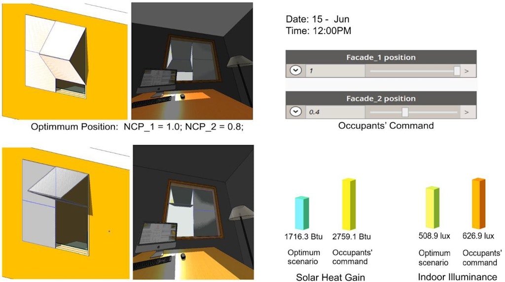
The dashboard serves as an interface for visualization of the potential for real-time control. In the dashboard, both the exterior view and interior view of the kinetic facades were displayed, which can change dynamically as the user adjusts the façade position. A slider that is used to control the facades’ position as well as the date and time also appeared in the dashboard. In addition, two key parameters, solar heat gain and indoor illuminance, are shown both textually and graphically. Two sets of colored 3D columns, one for solar heat gain and another for indoor illuminance, were used to compare and visualize how much discrepancy will have between the theoretical “optimum” façade position and the customized façade position that is overruled by the occupants (Fig. 8).
4. Evaluation of Proposed Workflow
The proposed methodology provides a comprehensive workflow for designing the kinetic façade system, analyzing its control strategy based on the performance on direct glare, energy efficiency and daylighting, and then evaluating and visualizing the effect of the occupants for real-time control. The determination of the control strategy of the kinetic facade and the dashboard are totally based on the case studies with specific building, façade component, location, and climate condition, and other data. It cannot be applied to other cases or projects directly. However, the proposed method is applicable for any shape of façade geometry and window configuration. It could be used during the early design stage of the kinetic facades to assess the potential benefits in terms of solar protection and daylighting. If more advanced daylighting simulation or energy simulation for the entire building are needed, other software programs should be applied.
The validation of several key parts of the proposed workflow including sun angle calculation, glass material properties calculation, dynamic shadow calculation, solar heat gain calculation, and indoor illuminance calculation were done in this chapter. It was demonstrated that the proposed workflow can get the correct or reasonable results for further analysis.
There are several limitations exist in the current workflow that could lead to the inefficiency work pace or inaccuracy of the simulation results, including the necessity of data processing in Excel, insufficient reference points for daylighting assessment, oversimplified glare assessment, limited daylight metrics, the low complexity of the façade control strategy, and limited simulation iteration. There are several aspects in the current methodology that could be improved by further research or work, including utilization of the generative design tools for doing data processing in a more efficient way, testing with the newer version of Dynamo which might be more stable and powerful, making the dashboard more informative graphically, integrating the virtual reality (VR) tools (e.g. Enscape for Revit) for a better visualization of the real-time control, extending the daylighting simulation node for more number of reference point, involving glare issue as a factor that could affect the occupants’ behavior apart from their preferences on the position of the shade, a more detailed analysis on several groups of façade that are controlled independently, and conducting simulation for a longer period of time in a year.
5. Conclusions and Future Work
The proposed workflow using Revit and Dynamo (with Python to create custom nodes) for the case study showed how BIM could be used for a multi-domain assessment of a kinetic façade based on energy performance (as determined by solar heat gain), daylighting (and excluding direct glare), and the occupant’s preferences. The workflow was used to create the kinetic façade model, to simulate its energy performance and daylighting performance parametrically, output the data for further analysis, and display with graphs the impact of the occupants. There still remain some deficiencies, including too few simulation days, not including a full glare analysis, and the relative inefficiency of the data processing process (with all numeric data in Excel instead of more advanced design tools). The case study supported and demonstrated the reliability and effectiveness of the proposed workflow. It may not be applied to all the real-world kinetic façade project directly. It just provides a potential efficient path to build upon. However, improvements can be made to the methodology development, method for data processing, and other features.
Revit and Dynamo are being used more and more in the AEC industry to achieve efficient and qualified design and data management. Compared with those traditional design and analysis tools such as Rhino and Grasshopper, Revit and Dynamo have a great advantage in terms of information and data rather than just geometry. In addition, Revit and Dynamo could be secondarily developed through the Revit API or Autodesk Design Script, which provides the possibility of doing customized automation or parametric analysis to facilitate the design process and realize what Rhino and Grasshopper can do. With an appropriate use of Dynamo, designers are able to design and analyze kinetic façade parametrically and also be aware of how occupants can affect the overall performance of the kinetic façade. The results can be informative to the owners or occupants giving them a brief idea that how they should operate the facades system and maximize its benefits.
In addition, being able to involve occupants in the façade control process and letting them override the façade control strategy can also help users to have a better understanding about how their behavior can affect the performance of the kinetic façade system as well as where does the performance discrepancies between the design and reality come from.
Rights and Permissions
"Python (programming language)". (2017, October 25). Retrieved from Wikipedia: https://en.wikipedia.org/wiki/Python_(programming_language)
"What is BIM". (2017). Retrieved from Autodesk: https://www.autodesk.com/solut... (2013). ASHRAE Handbook Fundamentals; American Society of Heating, Refrigerating and Air Conditioning Engineers: Atlanta, GA, USA; Chapter 15.
Boeykens, S. and Neuckermans, H. (2009). “Visual Programming in Architecture: Should Architects Be Trained As Programmers?” CAAD-Futures.
Crawley, D.B. and Hand, J. and Kummert, M. and Griffith, B.T. (2008) “Contrasting the capabilities of building energy performance simulation programs,” Building and Environment, 43 (4). pp. 661-673. ISSN 0360-1323
CTBUH (2013). “The Skyscraper Center – Al Bahar Tower.” Retrieved from CTBUH: http://www.skyscrapercenter.com/building/al-bahar-tower-1/9129
Grozdanic, L. (2016, November 7). “8 Impossibly Dynamic Facades That Were Actually Built.” Retrieved from Architizer: https://architizer.com/blog/8-impossibly-dynamic-facades-that-were-actually-built/
Haldi, F., and D. Robinson. 2010. “On the Unification of Thermal Perception and Adaptive Actions.” Building and Environment 45 (11): 2440–2457. doi:10.1016/j.buildenv.2010.05.010.
Kim, H., Asl, M. R., and Yan, W. (2015). “Parametric BIM-based Energy Simulation for Buildings with Complex Kinetic Facades,” Proceedings of the 33rd eCAADe Conference. 1, pp. 657-664. Vienna, Austria
Lee, Dong-Seok; Koo, Sung-Han; Seong, Yoon-Bok; and Jo, Jae-Hun (2016). “Evaluating Thermal and Lighting Energy Performance of Shading Devices on Kinetic Facade,”Sustainability, 8(9), 883.
Loonen, Roel C.G.M.; Favoino, Fabio; Hensen, Jan L.M.; and Overend, Mauro (2017) “Review of current status, requirements and opportunities for building performance simulation of adaptive facades,” Journal of Building Performance Simulation, 10:2, 205-223, DOI: 10.1080/19401493.2016.1152303
Mardaljevic, J., Heschong, L., and Lee, E. (2009). “Daylight metrics and energy savings,” Lighting Research & Technology, 41(3), 261-283.
Rahmani Asl, Mohammad; Bergin, M.; Menter, Adam; and Yan, Wei. (2014). “BIM-based Parametric Building Energy Performance Multi-Objective Optimization.” Listed in papers.cumincad.org.
Rea, M. S. (2000). The IESNA lighting handbook: reference & application.
Risen, Clay (2017, July 11). Award: Dynamic ETFE Facade. Retrieved from http://www.architectmagazine.com/awards/r-d-awards/award-dynamic-etfe-facade_o
Sharaidin, M. (2014). “Kinetic facades: towards design for environmental performance”, PhD Thesis, RMIT University.
Sun, Shang; Kensek, Karen; Noble, Douglas; and Schiler, Marc (2015), “A Method of Probabilistic Risk Assessment for Energy Performance and Cost Using Building Energy Simulation,” Energy and Buildings, September 2015.
Winkelmann FC, Selkowitz S. (1985). “Daylight simulation in the DOE-2 building energy analysis program,” Energy Building 8: 271–286.