The Glass Failure Prediction Model
Using Commercial Finite Element Software to Extend the Applicability of ASTM E 1300
Sign in and Register
Create an Account
Overview
Abstract
ASTM E 1300 Standard Practice for Determining Load Resistance (LR) of Glass in Buildings defines the load resistance of a glass construction as being the load which, upon its first occurrence, is associated with a nominal probability of breakage of 8 lites per 1000. In providing architectural glazing designers with values of load resistance for glass, ASTM E 1300 has grown into a huge document, with numerous charts to facilitate glass thickness selection and design. Use of these charts can be greatly abated by the application of the glass failure prediction model to stress analyses produced by commercial finite element method (FEM) software. The authors have accomplished this. They present comparisons between their analyses and values determined using ASTM E 1300 and finite difference software. These comparisons indicate that computations of load resistance obtained by applying the glass failure prediction model (GFPM) to output from commercially available FEM software are essentially the same as values from ASTM E 1300.
Authors

James G. Soules, P.E., S.E., P.Eng., SECB, F. SEI, F. ASCE
Graduate Student, Department of Civil, Environmental, and Construction Engineering
Texas Tech University
greg.soules@ttu.edu

Stephen M. Morse, P.E., Ph.D., A.M, ASTM
Assistant Professor of Civil and Environmental Engineering
Michigan Tech University
Stephen.M.Morse@ttu.edu

H. Scott Norville, P.E., Ph.D., F. FTI, F. ASCE, F. ASTM
Professor, Department of Civil, Environmental, and Construction Engineering
Texas Tech University
scott.norville@ttu.edu
Keywords
Background
Architectural glazing designers in the US and many other parts of the world use ASTM International Standard E1300 (ASTM, 2016), Standard Practice for Determining Load Resistance of Glass in Buildings as their primary source to determine LR of glazing and glazing constructions in buildings. ASTM International published the current edition of ASTM E1300 in 2016. The practice described in ASTM E 1300 (ASTM, 2016) applies only to flat glass constructions of rectangular shape. A nonlinear finite difference analysis model described in Vallabhan (1983) and Vallabhan and Chou (1986) serves as the stress analysis technique used in developing ASTM E 1300 (ASTM, 2016). Vallabhan (1983) and Vallabhan and Chou (1986) chose to use the finite difference approach due to the reduced computer resources required in comparison to those required to implement the finite element method at that time. Significant improvements have occurred in the tools available to perform nonlinear finite element analysis since Vallabhan (1983) and Vallabhan and Chou (1986) published their research. With the introduction of the analytical method in ASTM E 1300 (ASTM, 2016), engineers may now use commercially available finite element software to determine stresses and deflections in glass lites and constructions. The analytical method (ASTM, 2016) does not provide specific guidance to ensure that the results from a finite element analysis match similar results obtained from the chart-based method of ASTM E 1300 (ASTM, 2016). This paper presents specific guidance for modeling flat rectangular glass lites using commercially available finite element analysis software. Therefore, comparing the stresses and deflections from both nonlinear analysis methods to demonstrate the validity of the proposed finite element model is necessary. To further demonstrate the validity of the proposed finite element model, one applies the GFPM to the stress output from the finite element analysis and compares it to probabilities of breakage determined from either ASTM E 1300 (ASTM, 2016) or to applications of the GFPM to stress output from finite difference analyses.
The authors present a generic step-by-step procedure for modeling a flat rectangular glass lite using commercially available finite element software followed by a procedure for applying the GFPM developed by Beason and Morgan (1984) to the output of the analysis. Following this, they present comparisons between stresses, deflections, and probabilities of breakage from analyses based on the finite difference analyses (ASTM, 2016; Vallabhan, 1983; Vallabhan and Chou, 1986) and the finite element analyses developed for this study. They use the comparisons of stresses, deflections, and probabilities of breakage to demonstrate the appropriateness of the finite element model as the basis for the Analytical Method (ASTM, 2016).
Finite Element Model
The method goes into detail about the study and procedure – what tools, software or models were implemented, how results were ASTM E 1300 (ASTM, 2016) treats flat rectangular glass lites subjected to lateral loads as simply supported flat rectangular plates. The thin glass lites respond to the lateral loads in such a manner that large lateral deflections (relative to the thickness of the plate) occur. Large deflections induce tensile stresses in the middle fibers of the glass lite due to membrane action, i.e., stretching of the middle fiber. Bending stresses, tensile and compressive, in the outer fibers are superimposed onto the tensile stresses. Stretching of the middle fibers makes the glass lite stiffer than would be predicted by linear-elastic theory. Consequently, the load-deflection and load-stress relations are geometrically nonlinear (Young, Budynas, and Sadegh, 2012). Glass lites are typically supported by rigid window frames using neoprene or similar gasket material to support the glass in the frame. Glass lites in gasket supports are modeled as simply supported edges that cannot deflect out-of-plane, but which can rotate about the supports and deform in the plane of the glass lite (Vallabhan, 1983). Because gasket supports allow glass lite edges to deform in plane and provide no resistance in the plane of the glass lite, the tension caused by membrane behavior is resisted by circumferential compression (Young, Budynas, and Sadegh, 2012). The large lateral deflections experienced by the glass lites result in geometrically nonlinear behavior (Vallabhan 1983). Any finite element software used to analyze glass lites must therefore be able to model the nonlinear behavior of the glass lites. Fortunately, most commercially available finite element analysis programs have this ability.
In structural glazing applications, structural silicone sealant attaches glass lites to their supporting frames. At this point, ASTM E1300 (ASTM, 2016) treats structurally glazed lites as being simply supported although the structural silicone sealant provides resistance to both rotation and in-plane movement at the edges.
ASTM E1300 (ASTM, 2016) Section 6.3 introduces the analytical method that allows architectural glazing designers to determine stresses and deflections using an acceptable stress analysis procedure and probability of breakage by applying the GFPM the output of the stress analysis procedure. ASTM E1300 (ASTM, 2016) provides little specific guidance for modeling a glass lite in commercially available finite element analysis software. The authors provide the specific guidance missing from ASTM (ASTM, 2016) for modeling a rectangular glass light under uniform lateral load in commercially available finite element analysis software.
The bullet list below enumerates the major components that should be incorporated in a finite element model for a rectangular glass lite. The authors incorporate all these components into the finite element model developed for this study.
- Commercially available finite element software programs provide several elements with which to model a rectangular glass lite. The authors chose to use a 4-node, quadrilateral, stress/displacement shell element with reduced integration and finite membrane strains. This type of element produced results very close to those produced by the original finite difference model.
- Because the rectangular glass lite is symmetrical about two axes and is simply supported along all four edges, a quarter plate analysis should be used. The quarter plate analysis provides four times the mesh density required for a full plate analysis while using the same number of elements. Therefore, a quarter plate analysis provides greater computational efficiency than does a full plate analysis.
- In several model runs in this study the authors used 700 to 1000 nodes. Node numbers in this range resulted in consistent results. The authors suggest using numbers of nodes in this range for quarter plate analyses.
- Figure 1 shows the edge conditions and symmetry conditions in the quarter plate analyses. The authors recommend these edge and symmetry conditions for rectangular glass lites simply supported along all four edges.
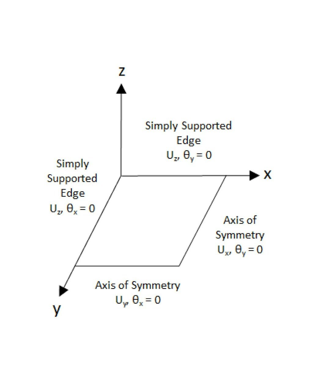
- Consistent with values used for glass in ASTM E1300 (ASTM, 2016) the authors formulated the model using an elastic, isotropic material with Young’s Modulus of 71.7 x 10³ MPa (10.4 x 10⁶ psi) and Poisson’s Ratio of 0.22.
- The finite element software nonlinear geometry functionality must be turned on with an appropriate increment set for use in the nonlinear iterative solution.
- Commercially available finite element analysis software typically requires the use of consistent units. The authors used $P_{a}$ or multiples thereof for the uniform pressure load, Young’s Modulus, and resulting principal stresses. They used glass lite dimensions in millimeters.
Commercially available finite element software can report several different types of results. Most commercially available finite element programs default to reporting von Mises stresses. For use with the GFPM, the in-plane principal stresses are required. The principal stresses must be reported at the finite element nodes for use with the GFPM. The next section discusses application of the GFPM to the principal stresses determined from the finite element analysis.
Application of the GFPM
ASTM E1300 (ASTM, 2016) Annex A2 provides a procedure to determine the probability of breakage ($P_{b}$) of monolithic glass lites using the GFPM developed by Beason and Morgan (1984). The equation for the probability of breakage of monolithic glass lites from Beason and Morgan (1984) is:
$$P_{b}=1- e^{-B}\tag{1}$$
Where $P_{b}$ denotes the probability of breakage and B denotes a risk function described by the following integral:
$$B=k \cdot \left( \frac{t_{d}}{60} \right) ^{\frac{m}{16}} \int _{0}^{a} \int _{0}^{b} \left[ c \left( \text{x, y} \right) \cdot \sigma _{\max } \left( \text{q, x, y} \right) \right] ^{m}~dydx \tag{2}$$
In Equation 2, $^{m}$ and $k$ denote surface flaw parameters,
$t_{d}$ denotes the time duration of the loading,
$n$ denotes the static fatigue constant for glass, taken as 16 herein,
$a$ and $b$ denote the rectangular dimensions of the glass lite
$c \left( \text{x, y} \right)$ denotes a biaxial stress correction factor,
$\sigma _{\max } \left( \text{q, x, y} \right)$ denotes the maximum in-plane principal stress
In numerical analyses with stresses defined at discrete points, the summation in Equation 3 replaces the risk function above. In addition, the analytical method incorporates residual compressive surface stress (RCSS) into the risk function to facilitate computations for heat treated glass.
$$B=k⋅ \sum _{i=1}^{N} \left( \left( c_{i}⋅ \left( \frac{t_{d}}{60s} \right) ^{\frac{1}{n}}⋅ \left( \sigma _{\max _{i}}-RCSS \right) \right) ^{m}⋅A_{i} \right)\tag{3}$$
with:
\begin{align}
c_{i}=&-0.005⋅r_{i}^{6}+0.022⋅r_{i}^{5}+0.055⋅r_{i}^{4} \\
&+0.039⋅r_{i}^{3}+0.031⋅r_{i}^{2}+0.06⋅r_{i}+0.8\tag{4}
\end{align}
$$r_{i}=\frac{ \left( \sigma _{\min _{i}}-RCSS \right) }{ \left( \sigma _{\max _{i}}-RCSS \right) }\tag{5}$$
where:
$c_{i}$ denotes a biaxial stress correction factor at the ith node,
$k$ denotes a surface flaw parameter equal to 2.86 × 10-53 N-7 m12 (1.365 x 10⁻²⁹ in12 lbf-7),
$m$ denotes a second surface flaw parameter taken as 7,
N denotes the number of nodes at which stress values were computed,
$t_{d}$ denotes duration of loading (taken as 3 sec for this study); sec,
$n$ denotes the static fatigue constant taken as 16 in ASTM E 1300(ASTM, 2016),
$\sigma _{\max _{i}}$ denotes maximum principal stress at the ith node; Pa (psi),
$\sigma _{\min _{i}}$ denotes minimum principal stress at the ith node; Pa (psi),
$RCSS$ denotes residual compressive surface stress; 0 Pa (0 psi) for annealed glass, 24.0 MPa (3,500 psi) for heat strengthened glass, 69.0 MPa (10,000 psi) for fully tempered glass, and
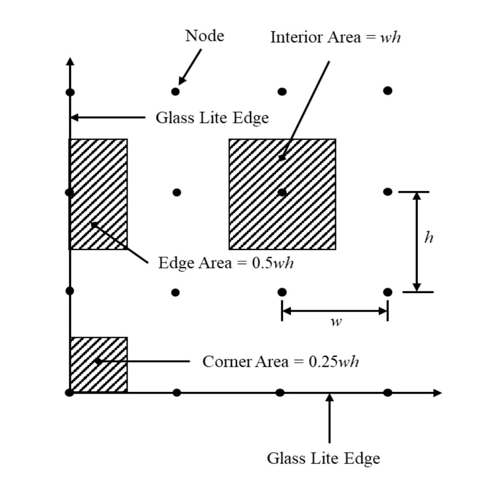
${A_i}$ denotes the tributary area associated with to the ith node, m2 (in2)
The procedure from ASTM E 1300 (ASTM, 2016) Annex 2 is easily implemented using a spreadsheet. However, the following clarifications are required to implement the above procedure to the output of the finite element model:
- Because the model uses a quarter plate in the analysis, the value of B obtained from a quarter plate analysis must be multiplied by a factor of 4.0.
- If the analysis is made using SI units, the values $\sigma _{\max _{i}}$ $\sigma _{\min _{i}}$, and RCSS must be in Pa or multiples thereof.
- The minimum value of ri is set at -1.0, regardless of values on Eqn. 5 (Morse, 2018).
- Figure 2 shows the different possible tributary area, Ai, configurations associated with nodes comprising the model.
Morse (2018) presents numerical examples using the above procedure for determining the probability of breakage (Pb).
Results
The authors used the finite element model to compute in-plane maximum principal stresses and maximum deflections for 29 different geometries (width, height, and thickness) for three different load levels (87 total analyses) in order to demonstrate its validity. They applied the GFPM to the stress output and determined probabilities of breakage using the above equations for each of the 87 cases. Table 1 shows the geometries used. The three load levels comprised the LR of the glass lite from ASTM (ASTM, 2016), 0.5 times LR, and 2 times LR. Table 2 presents comparisons between maximum principal stresses as computed by the finite difference model and the finite element model for representative plate geometries using LR. Table 3 presents comparisons between maximum deflections as computed by the finite difference model and the finite element model for representative plate geometries using LR. Table 4 presents comparisons between probabilities of breakage as computed by the finite difference model and the finite element model for representative plate geometries using LR. Table 5 shows the average percent difference in these values based on all 87 analyses. The very small differences between the values determined using the finite difference method and the values determined using the finite element method show that both proposed methods agree very well. Hence, the finite element model developed herein can be used in the analytical procedure in ASTM E 1300 (ASTM, 2016) to determine architectural glass LR.
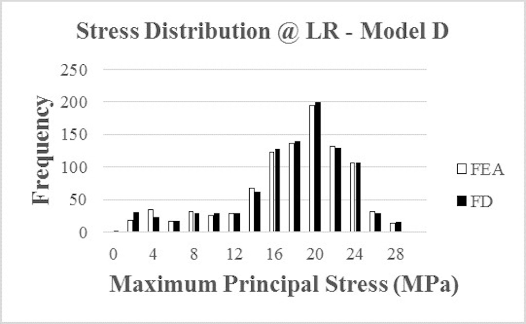
As an additional indication of the validity of the proposed finite element model, the author compared distributions of maximum principal stresses from the finite element analysis and the finite difference analysis. For Model D, maximum principal stresses from a representative finite element analysis and a finite difference analysis that forms the basis of ASTM (2016) are plotted as histograms (Figure 3). A review of Figure 3 shows an almost identical distribution of stresses between the two different methods. Model D generates almost identical results from both the finite element analysis and the finite different analysis. The correlation of stresses demonstrated by these two sets of distributions is a strong indicator that both analysis methods are modeling the same behavior in the glass lite. This is another indicator that the proposed finite element model is sufficiently accurate for use in designing glass lites to meet the requirements of ASTM (2016).
Table 1. Glass Lite Geometry
Model | Short Dimension (mm) | Long Dimension (mm) | Nominal Thickness (mm) | Minimum Thickness (mm) | |
A | 965 | 1930 | 6 | 5.56 | |
B | 965 | 1930 | 8 | 7.42 | |
C | 965 | 1930 | 10 | 9.02 | |
D | 1676 | 1676 | 5 | 4.57 | |
E | 1676 | 1676 | 6 | 5.56 | |
F | 1676 | 1676 | 8 | 7.42 | |
G | 1676 | 1676 | 10 | 9.02 | |
H | 1219 | 1803 | 5 | 4.57 | |
I | 1219 | 1803 | 6 | 5.56 | |
J | 1219 | 1803 | 8 | 7.42 | |
K | 1219 | 1803 | 10 | 9.02 | |
L | 1778 | 1956 | 5 | 4.57 | |
M | 1778 | 1956 | 6 | 5.56 | |
N | 1778 | 1956 | 8 | 7.42 | |
O | 1778 | 1956 | 10 | 9.02 | |
P | 762 | 7620 | 6 | 5.56 | |
Q | 762 | 7620 | 8 | 7.42 | |
R | 762 | 7620 | 10 | 9.02 | |
S | 762 | 7620 | 12 | 11.91 | |
T | 254 | 1829 | 6 | 5.56 | |
U | 254 | 1829 | 10 | 9.02 | |
V | 381 | 1905 | 5 | 4.57 | |
W | 381 | 1905 | 6 | 5.56 | |
X | 381 | 1905 | 8 | 7.42 | |
Y | 381 | 1905 | 10 | 9.02 | |
Z | 381 | 1905 | 19 | 18.26 | |
AA | 2540 | 2540 | 16 | 15.11 | |
BB | 2540 | 2540 | 19 | 18.26 | |
CC | 2286 | 3048 | 12 | 11.91 |
Table 2. Comparison of Maximum Principal Stress
Finite Difference Model | Finite Element Model | |||
Model | LR (kPa) | Maximum Stress @ LR (MPa) | Maximum Stress @ LR (MPa) | % Dif |
A | 2.0 | 27.12 | 27.16 | -0.1 |
D | 1.4 | 27.62 | 27.45 | 0.6 |
I | 2.1 | 22.90 | 23.15 | -1.1 |
N | 2.1 | 22.28 | 22.55 | -1.2 |
Q | 2.9 | 22.78 | 22.64 | 0.6 |
T | 21.3 | 33.24 | 33.10 | 0.4 |
Z | 97.2 | 31.64 | 31.58 | 0.2 |
CC | 2.0 | 19.92 | 19.88 | 0.2 |
Table 3. Comparison of Maximum Deflection
ASTM E1300 | FEA Model | |||
Model | LR (kPa) | Maximum Deflection @ LR (mm) | Maximum Deflection @ LR (mm) | % Dif |
A | 2.0 | 12.5 | 12.5 | -0.2 |
D | 1.4 | 20.8 | 20.8 | 0.0 |
I | 2.1 | 16.4 | 16.4 | 0.2 |
N | 2.1 | 19.5 | 19.5 | -0.1 |
Q | 2.9 | 4.9 | 4.9 | 0.7 |
T | 21.3 | 1.1 | 1.1 | 0.3 |
Z | 97.2 | 0.7 | 0.7 | -0.3 |
CC | 2.0 | 22.5 | 21.7 | 3.5 |
Table 4. Comparison of Probability of Breakage ($P_{b}$)
ASTM E1300 | FEA Model | |||
Model | LR (kPa) | $P_{b}$ @ LR | $P_{b}$ @ LR | % Dif |
A | 2.0 | 0.0082 | 0.0084 | -1.5 |
D | 1.4 | 0.0082 | 0.0082 | 0.0 |
I | 2.1 | 0.0080 | 0.0080 | 0.2 |
N | 2.1 | 0.0081 | 0.0081 | 0.0 |
Q | 2.9 | 0.0086 | 0.0081 | 4.9 |
T | 21.3 | 0.0087 | 0.0084 | 2.8 |
Z | 97.2 | 0.0080 | 0.0080 | -0.1 |
CC | 2.0 | 0.0079 | 0.0078 | 1.7 |
Table 5. Average % Difference - ASTM E1300 vs. FEA Model (All Load Cases)
Attribute | Avg. % Dif |
Probability of Breakage ($P_{b}$) | 1.5 |
Maximum Principal Stress | 0.1 |
Maximum Deflection | -0.3 |
The differences between the values determined by the proposed finite element model and finite difference analyses that form the basis of ASTM E 1300 (ASTM, 2016) are very minor. They arise primarily from differences in modeling the boundary conditions. The finite difference model assumes zero stresses near the supported edges while the finite element model correctly determines compressive stresses near the supported edges developed to resist the tension caused by membrane behavior (Young, Budynas, and Sadegh, 2012). Therefore, the proposed finite element model provides a better representation of the boundary conditions than does the finite difference method. The probability of breakage is quite sensitive to the variation in stress in the glass lite. The authors observed from the analyses that differences in the maximum principal stress on the order of 2 or 3 percent can cause differences in the probability of breakage of 15 to 16 percent. The results shown for Model B in Tables 2 through 4 show such an example. While on the surface, a difference of 15 to 16 percent in the probability of breakage may seem significant, it is not. A 2 or 3 percent variation in the load applied will result in this level of difference in the probability of breakage. In the NFL charts of ASTM E 1300 (ASTM, 2016), this difference represents the width of a pencil line.
Conclusions and Future Work
Based on the comparisons made in this paper between the proposed finite element model and the finite difference method used as the basis of ASTM E 1300 (ASTM, 2016), the proposed finite element model results in maximum principal stresses, maximum deflections, and probabilities of breakage nearly identical to those produced using the finite difference model that served as the basic stress analysis for ASTM E 1300 (ASTM, 2016). The very small differences between the values determined using the finite difference method and the values determined using the finite element method show that the proposed finite element model is sufficiently accurate for use in designing glass lites with commercially available finite element software to meet the requirements of ASTM E 1300 (ASTM, 2016)
Future efforts using finite element based modeling will include analysis and design of flat glass with non-rectangular shapes and curved glass. This work will obviate the use of the numerous charts and tables in ASTM E 1300 (ASTM, 2016) while greatly extending its applicability.
Rights and Permissions
ASTM (2016). “Standard practice for determining load resistance of glass in buildings.” ASTM E1300-16, ASTM International, West Conshohocken, PA.
Beason, W. L., and Morgan, J. R. (1984). “Glass failure prediction model,” J. Struct. Eng., 110(2), 197-212.
Morse, S. M. (2018). “New provisions in ASTM E1300-16: A comparison of the basic and new analytical procedures for determining the load resistance of window glass”, Proc., Facade Tectonics 2018 World Congress, D. Noble, K. Kensek, and M. Elder, ed., Vol. 2, Tectonic Press, Los Angeles, CA, 529-541.
Vallabhan, C. V. G. (1983). “Interactive analysis of nonlinear glass plates,” J. Struct. Eng., 109(2). 489–502.
Vallabhan, C.V.G., and Chou, G. D. (1986). “Interactive nonlinear analysis of insulating glass units,” J. Struct. Eng., 112(6). 1313–1326.
Young, W. C., Budynas, R. G., and Sadegh, A.M. (2012). Roark’s formulas for stress and strain, 8thedition, McGraw-Hill, New York, NY.