Multilayer Design Technique in the Metal Facades
Sign in and Register
Create an Account
Overview
Abstract
Multilayer design technique in metal facades is introduced in this paper. Generally, in this technique, a metal facade is designed in the fourth layer. Base element, support bracket, vertical/horizontal substructure and final decorative panels are forth layers in this technique. The first layer is the base element of the metal facade that is attached to the main structure by the on-site welding process. The second layer is a support bracket that is composed of sheet metal with I-Shape geometry. The third layer is vertical/horizontal substructure that is manufactured by sheet metal process with the T-shape and U-shape geometry. Finally, the last layer is the decorative panel that mostly is a sheet metal folded panel with laser cut texture. All layers are connected together in the site with the standard stainless steel bolts and nuts. Some criteria for the geometry and cross section design in these layers are; minimization of the raw material, ergonomic installation, to be modular, coating all surface, fast installation, able to CNC based manufacture, adjustable for sharp installation, easily replaceable, weight minimization, omitting the storage limitation and the complex shape metal facade limitation. Analysis of the results in the several installed projects proofs that using this technique reduces the runtime and final project cost. Also, final geometrical quality and durability of the installed metal facade are increased.
Authors

Soleyman Arebi
Arvin-Uzman Industrial Ltd
s.arebi@yahoo.com
Kiamoosh Farhang Djavid
Arvin-Uzman Industrial Ltd
kian@westelite.ca

Naser Paryab
Arvin-Uzman Industrial Ltd
paryab@arvin-uzman.com

Bahram Allahyari Emadi
Arvin-Uzman Industrial Ltd
allahyari@arvin-uzman.com

Mohammad Manafazadeh
manafzadeh@arvin-uzman.com
Arvin-Uzman Industrial Ltd
manafzadeh@arvin-uzman.com

Hossein Mahmoudi
Baran Office
Office.baran@yahoo.com
Keywords
Introduction and Background
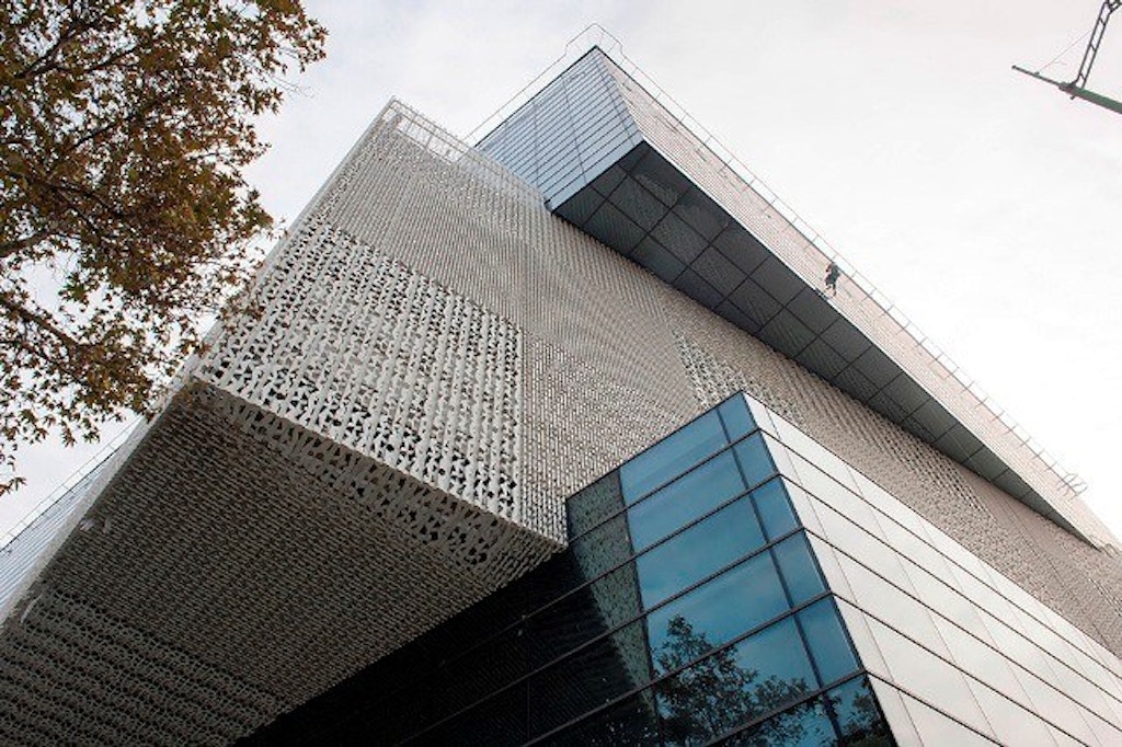
Introduction-Metal Facade Advantages
Metal facade panels can be used to dramatically enhance the outdoor appearance of many different types of buildings. Metal building facades can reduce energy usage and provide
Access Restricted
Method
Method-Multilayer Technique Introduction
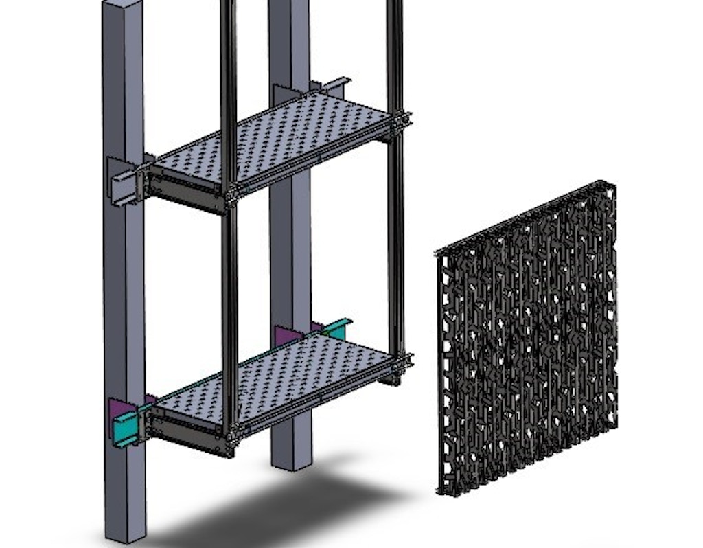
Generally, in the multi-layered technique, a metal façade is designed in the fourth layer. Base element, support bracket, vertical/horizontal substructure and final decorative panels are four layers in this technique (Fig.1). The first layer is the base element of the metal façade that is attached to the main structure by the welding process. The second layer is a support bracket that is composed of sheet metal process with I-Shape geometry. The third layer is vertical/horizontal substructure that is manufactured by sheet metal process with the T-shape and U-shape geometry. Finally, the last layer is the decorative panel that mostly is a sheet metal bent panel with laser cut texture. All layers are connected together in the site with the standard stainless steel bolts and nuts.
Method-Layer 1: Base Element
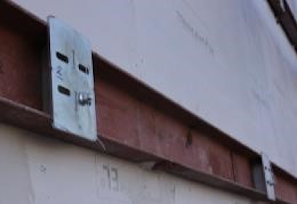
The first layer is the base element of the metal façade that is attached to the main structure by the welding process. First, the standard U channel is sheared with high precision. Finally, it is installed on each level of the floors. In metal buildings, the connection of this layer is done with the aid of a special bracket. It is used in concrete buildings with the help of an intermediate plate connected with the bullet to the level of the building. At this stage, before the final welding of the connection plate to the profile, the necessary measurements are made.
Details of base installation are shown in Figure 2.
As it is shown in the Figure 2, this layer is composed of three parts: Initial bracket, U channel, and support bracket base. The initial bracket is made of steel sheet with 8-10 mm thickness (according to façade weight). Also, support bracket base is laser cut sheet metal with holes for connecting the support bracket to it. Also, there are some welded nuts on the support bracket base for connecting the spandrel clad in the second layer. The support bracket base is coated with hot-deep galvanized. Main Specifications of this technique are described as following:
- High-speed installation.
- Lower cost due to the use of U channel profile.
- The ability to adjust the base layer and compensate errors from the structure misalignment.
- Scalable for various façade type (for each facade with different weights, only sizes are designed and changed).
- Can be installed without scaffolding (climber is enough).
- The ability to spray fireproof material on it.
- Access to bolt and nut connection between support bracket and its bracket base (due to use U channel profile).
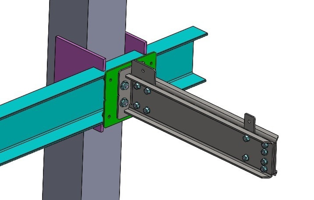
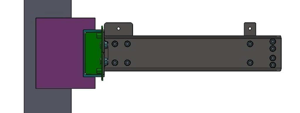
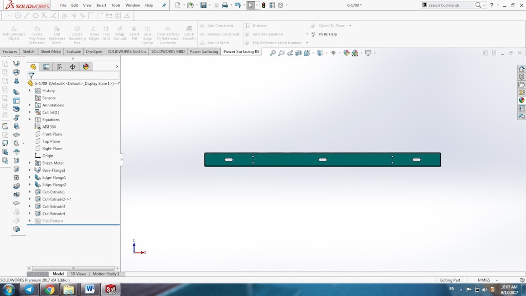
Method-Layer 1: Support Bracket
This layer is pre-fabricated I-shape that is made using the sheet metal process. At first, roll sheet is sheared by laser cutting machine. Then I-shape is generated by bending machine. Finally, electrostatic powder coating or hot-deep galvanized are used for final coating. Stainless steel nuts and bolts are used for final assembling in the factory and site. The walkway is installed on this support bracket. The walkway is made using the sheet metal process. For manufacturing this part, galvanized sheet metal is punched and forming tool is used to create brush surface. Details of support bracket are shown in Figure 3.
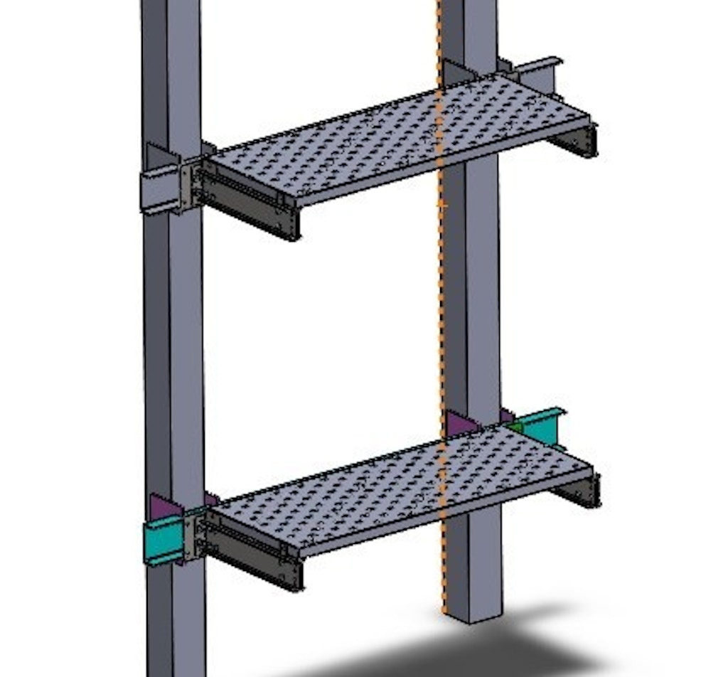
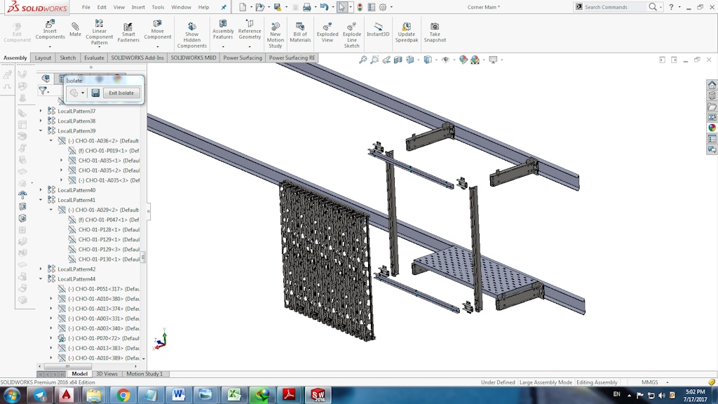
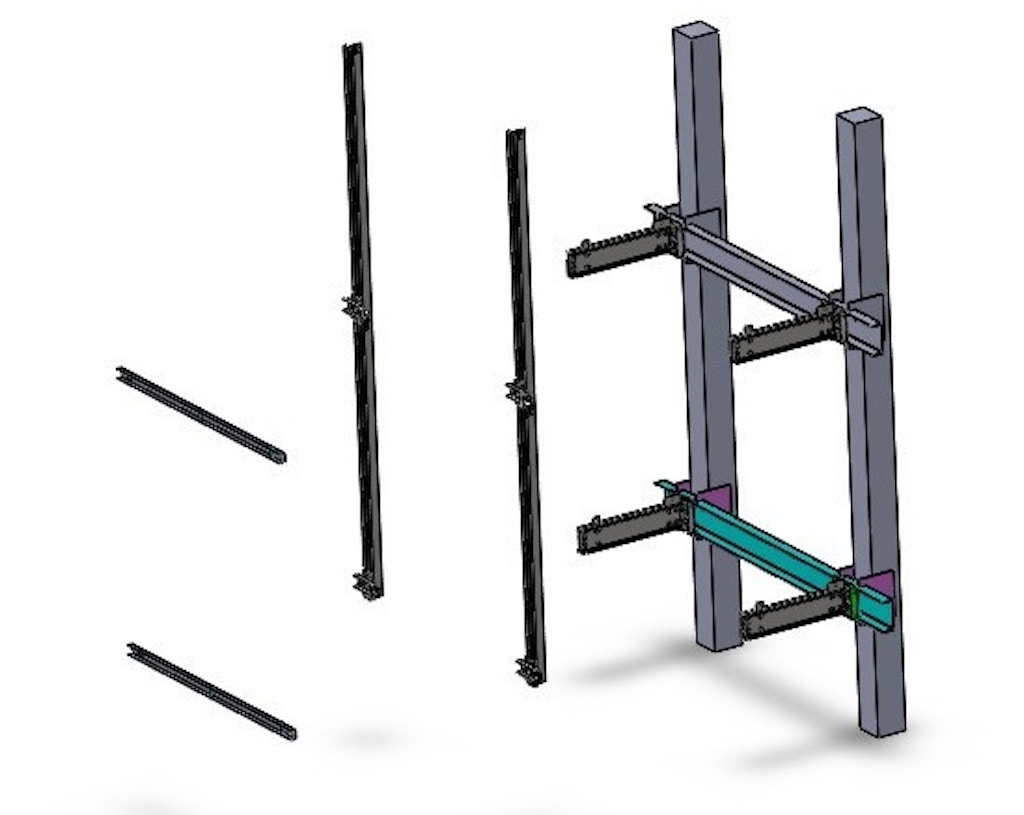
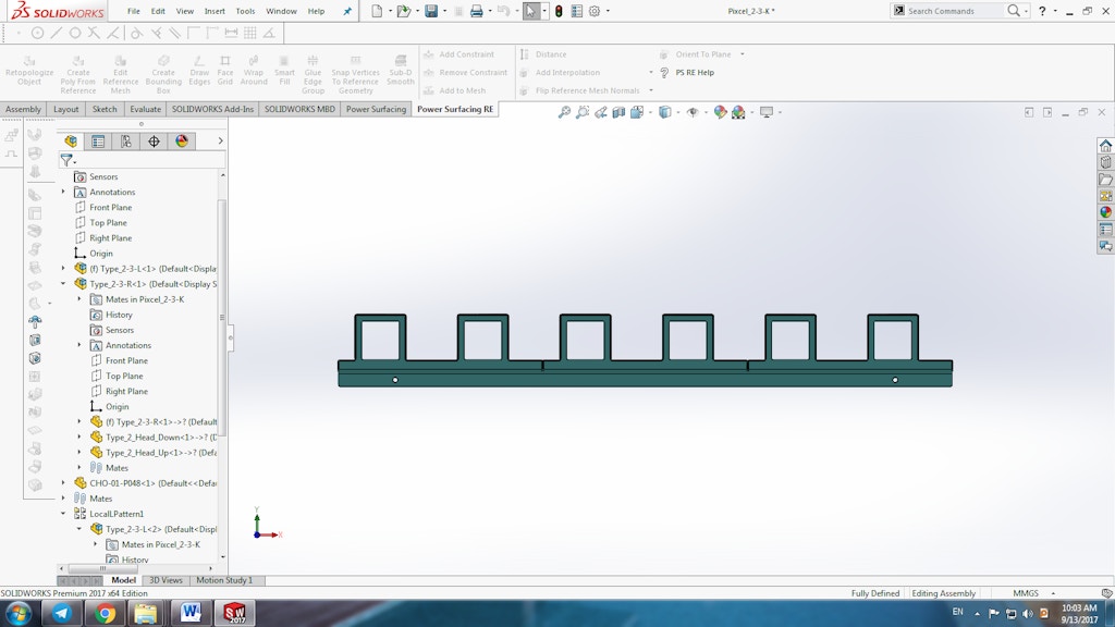
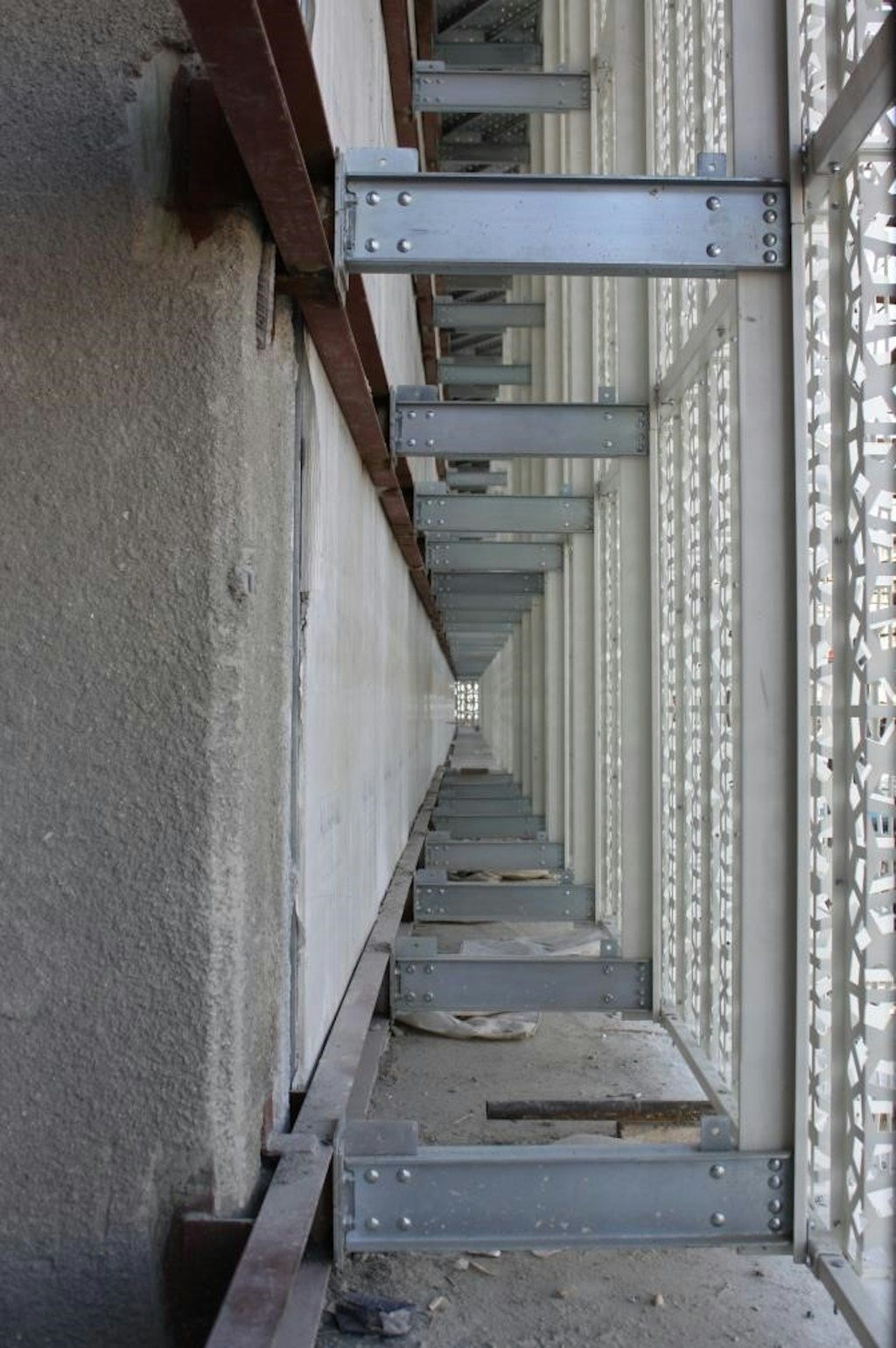
Method-Layer 3: Vertical/Horizontal Substructure
This layer consists of T-shape vertical and U-shape horizontal brackets. Both brackets are produced using a sheet metal process. These parts are produced at the factory and then shipped to the site. Finally, the support bracket is connected to bolts and nuts. At this stage, after the final connection, the position of the parts is checked in all three horizontal and vertical and depth directions and it is corrected if necessary. Details of this layer are shown in Figure 4.
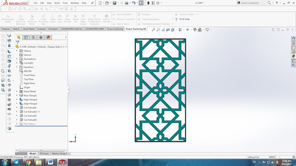
Method-Layer 4: Final Decorative Panels
The final layer contains the main façade, which includes decorative panels. These panels are made of the sheet metal process. A laser cutting machine is used for creating custom texture. Then, a CNC bending machine is used for folding the texturized panel. Final coating mostly is powder coating with customized code. On-site, panels are installed to the previous layer with stainless steel nuts and bolts. Details of this layer are shown in Figure 5.
Results for Structural Analysis and Dimensions
To design the exact dimensions of the layers elements in each metal façade, structural analysis is performed. Wind force and earthquake forces are considered in the calculations. According to allowable deflection and vibration frequency, the thickness of the sheet metal parts is identified. For example, results for typical metal façade with the Iranian Gerehkari texture are shown in Figure 6.
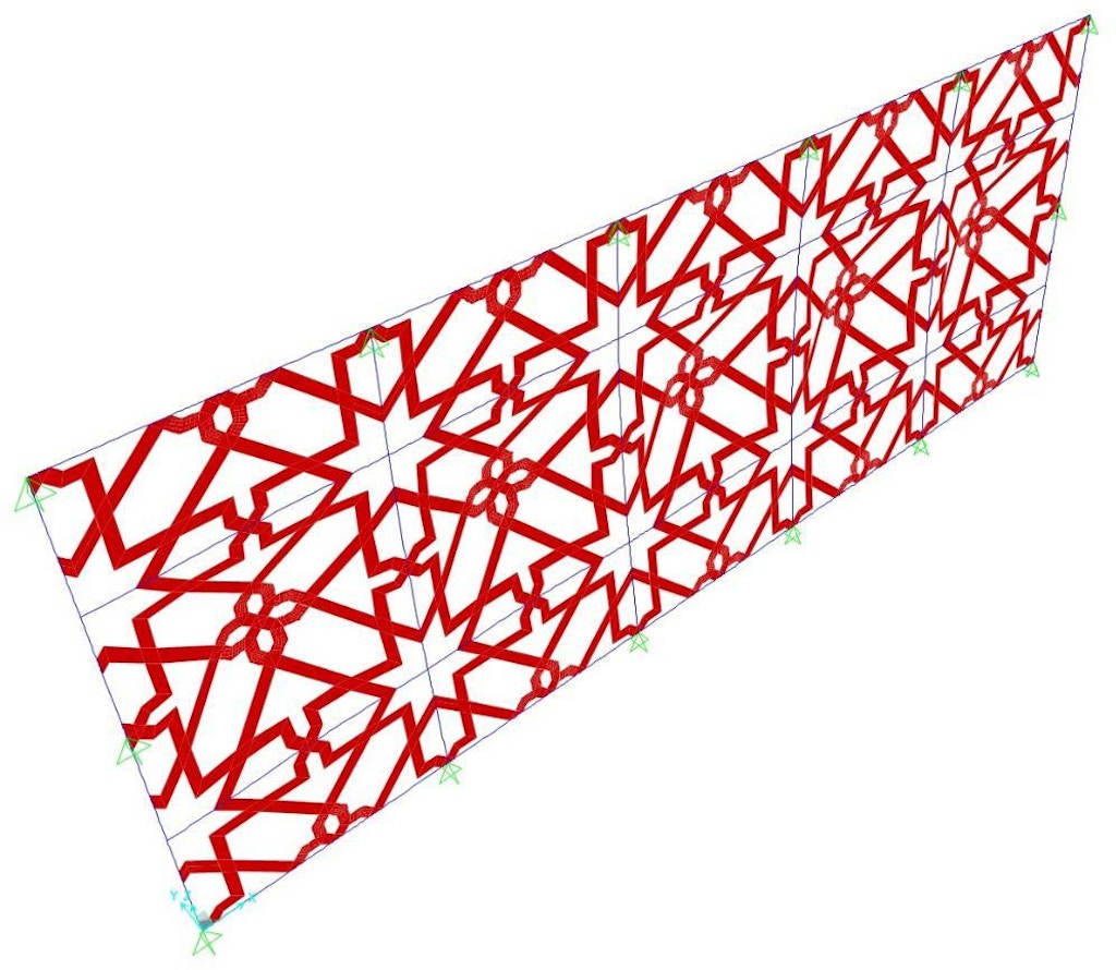
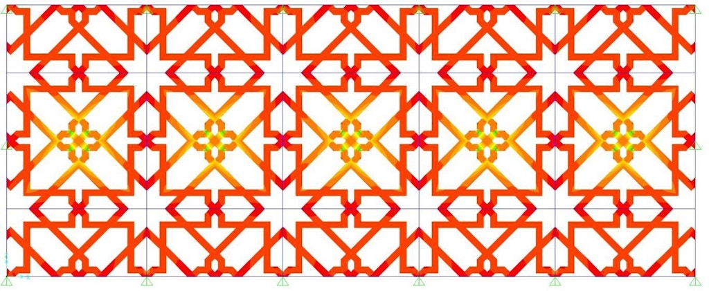
Size of this panel is 9m×3.8m. The maximum deflection in this metal façade is 53 mm and period of oscillation is 0.163 second. Based on the structural analysis results, the thickness of sheet metal parts in layers 1-4 is designed. The results for the metal facades in the common size (2m×2m panel size) are reported in the next sections.
Results - Layer 4
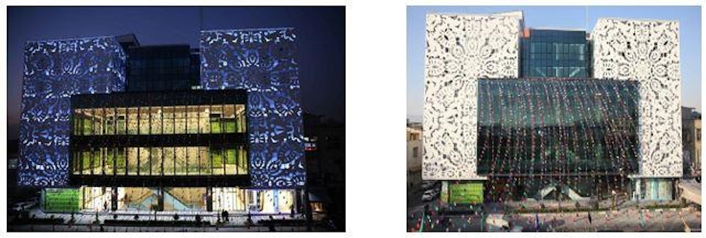
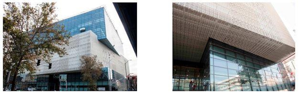
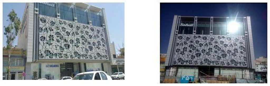
For the common size, steel, galvanized steel or 6030 aluminum alloy sheets with the 2 - 4 mm in thickness are used. For common texture with 62 percent minus area, a steel sheet with the 4 mm thickness is used. Two types of the façade panels are shown in Figure 7.
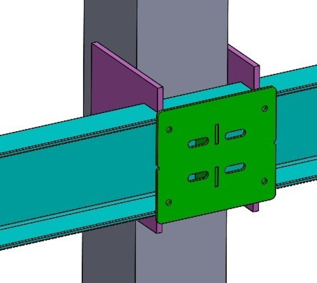
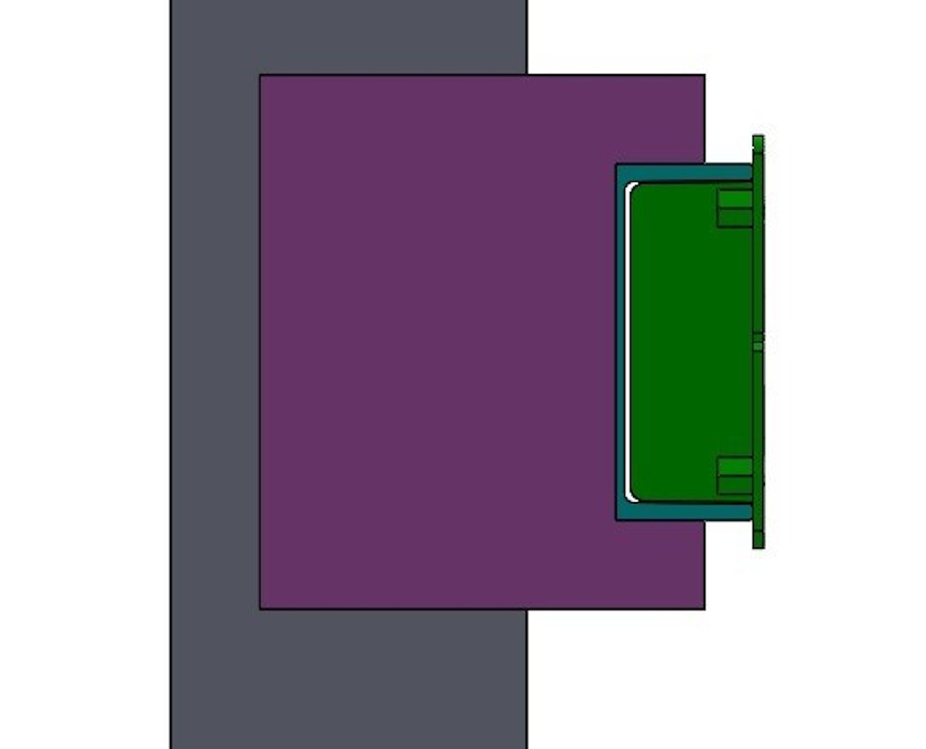
Results - Layer 3
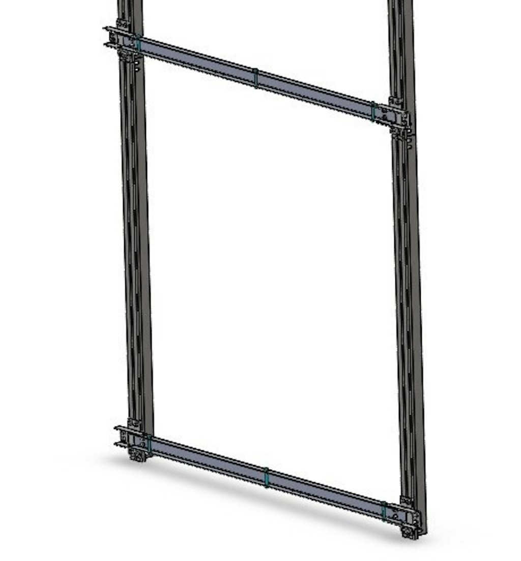
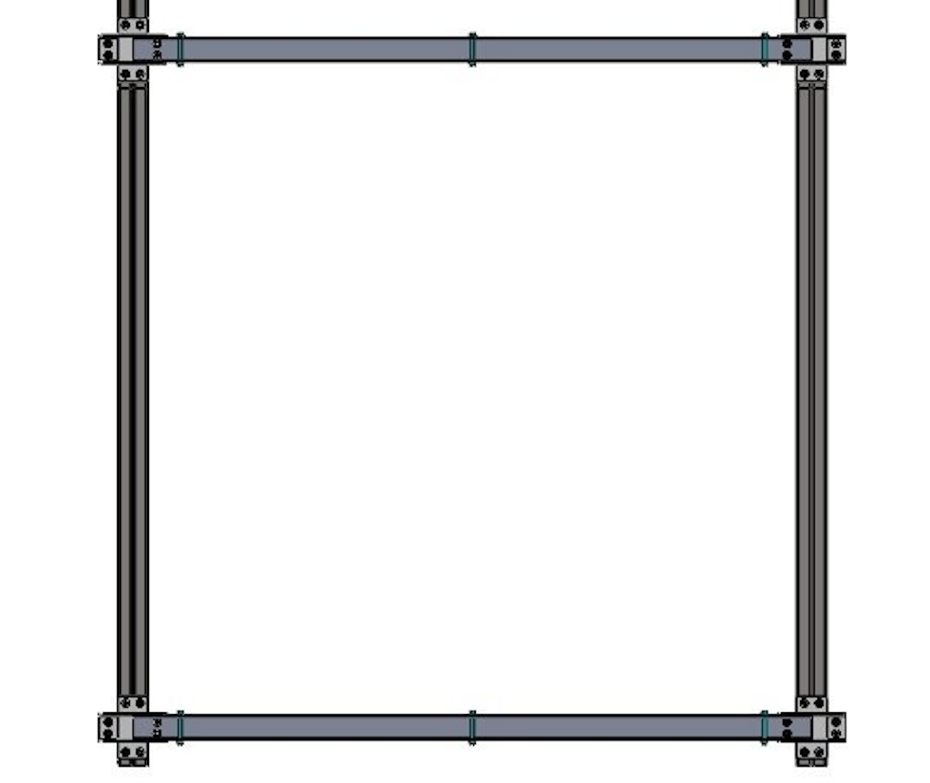
Vertical and horizontal substructures are folded sheets with T and U-shape brackets. For the common size of façade panels, steel sheet with 2mm thickness is used for this layer. In this layer all parts connected with the stainless steel bolts and nuts. In the connection nodes, bolts are installed in the oval hole to allow adjustment of the substructure in three directions. Also, the final formed grid of horizontal and vertical brackets forms a stable structure. Details are shown in Figure 8.
Figure 8: T and U shape of vertical and horizontal brackets.
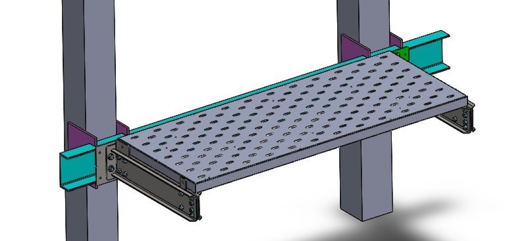
Results - Layer 2
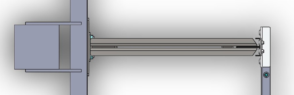
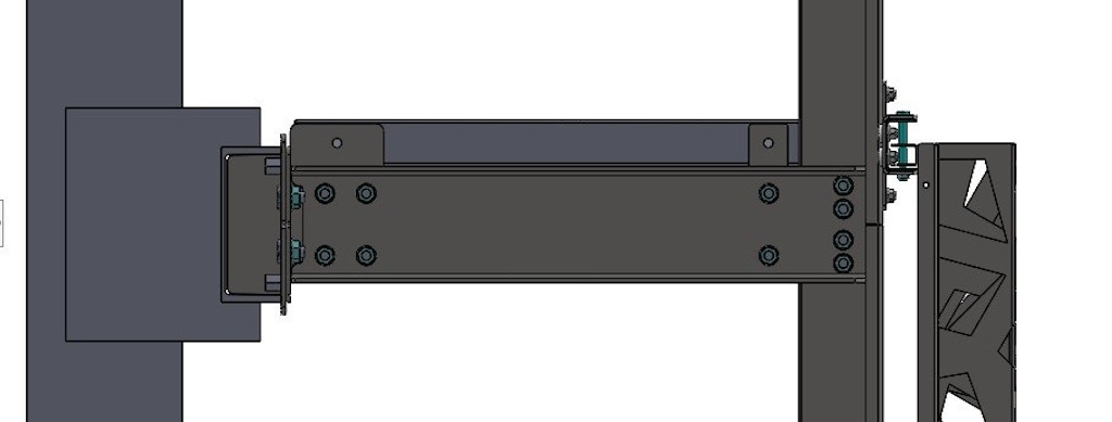
The support bracket is an I-shaped bracket that is assembled with bolt and nuts. For the common size of façade panels, Steel sheet with 5mm thickness is used for this layer. This I-shaped has been designed for bending capacity, walkway base and fasteners installation. The walkway is designed for tolerating a 150 kg person. The walkway is 2 mm galvanized sheet with 60 cm width. Details are shown in Figure 9.
Figure 9: The support bracket and walkway.
Results - Layer 1
The weight of the entire facade is tolerated by this layer. According to the structural point of view, the critical point is the support plate. For the common size of façade panels, the total weight of layers 2 - 4 is 50 . Wind force and weight of layers 2-4 are tolerated by this layer.
Explanation
Explanation - Total Duration of the Reference Projects
For evaluation of the proposed technique, the total time duration of the selected reference projects is reported in Table.1.
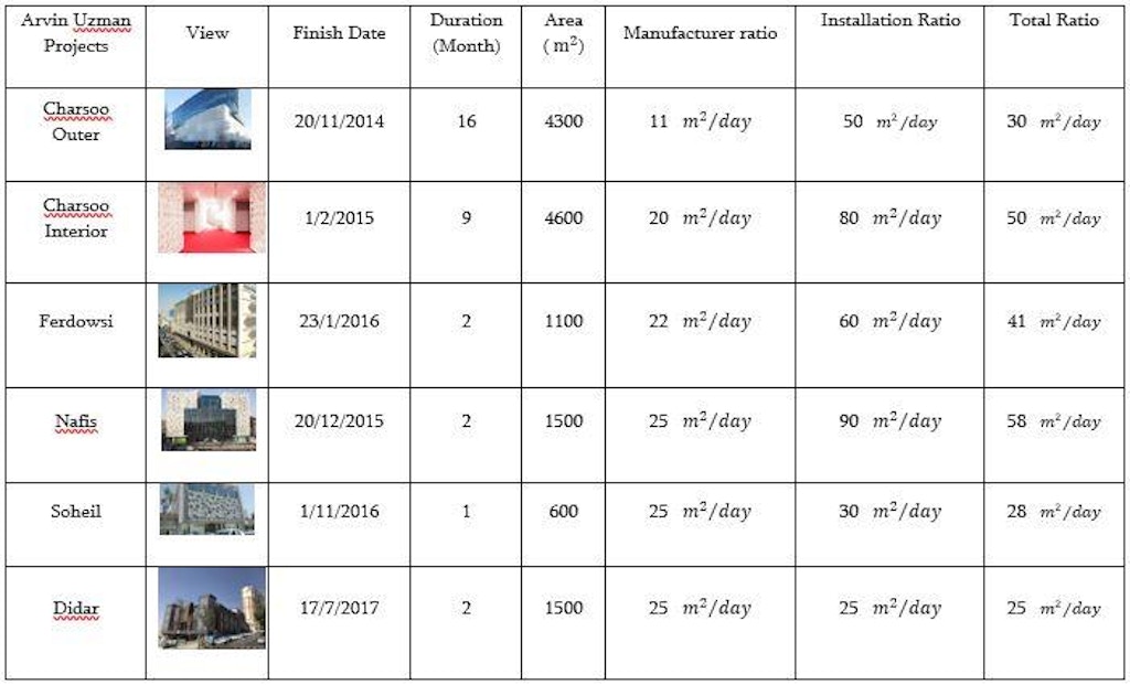
Also, manufacture, installation and total ration are reported here. Results show that the average total ration for various projects is 30. Comparing to the other techniques that are used in Iran, this speed is three times faster. In addition to other advantages mentioned, the total cost of this method is also lower compared with the other methods. The following is a graphic illustration of the selected reference projects.
Conclusion and Future Work
The multilayer technique in the architectural metal façade design is introduced in this paper. At the first, four layers of design technique are introduced. Sheet metal process is introduced as
Access Restricted
Acknowledgements
The reference projects could not be realized without the efforts of the workers in the factory and site. Thanks to the Arvin Uzman Company workers (Authors Company) in the factory and installation site.
Rights and Permissions
Ajla Aksamija, “Thermal and energy performance in different climate types”, Facade Tectonics world congress, (2016), Los Angeles.
Brandl, D., T. Mach, M. Grobbauer, and C. Hochenauer. “Analysis of Ventilation Effects and the Thermal Behavior of Multifunctional Facade Elements with 3D CFD models.” Energy and Buildings 85 (2014): 305–320.
Christoph Paech, Structural membranes used in modern building facades, Procedia Engineering 155 (2016) 61 – 70.
Gökhan Karakuş, Doha Tower, 2016, On Site Review Report.
Harris Poirazis, Double Skin Facades, A Literature Review, A report of IEA SHC Task 34 ECBCS Annex 43, 2006.
Jesús M. Blanco, Pedro Arriaga, Eduardo Rojí, Jesús Cuadrado, Investigating the thermal behavior of double-skin perforated. sheet facades: Part A: Model characterization and validation procedure, Building and Environment 82 (2014)
John Neary, "Integrating structure and cladding" Facade Tectonics world congress, (2016), Los Angeles.
Michael Johann Paar, Alexander Petutschnig, Biomimetic inspired, natural ventilated facade – A conceptual study, Journal of Facade Design and Engineering 4 (2016) 131–142.